Fixing structure of fiber cover

A fixed structure, fibrous technology, applied in the field of fixed structure of fibrous overlays, can solve the problems of prolonged working time, increased oil cylinder capacity, increased equipment costs, etc., and achieves the effect of strong joint strength

Inactive Publication Date: 2006-07-12
KASAI KOGYO CO LTD
View PDF1 Cites 4 Cited by
  • Summary
  • Abstract
  • Description
  • Claims
  • Application Information

AI Technical Summary

Problems solved by technology

[0006] However, since the sound-absorbing member 2 is ultrasonically welded and processed on the interior 1 using the ultrasonic horn 4 having the concave-convex surface 4a as the processed surface, it is necessary to apply a large pressure to the ultrasonic horn 4 so that the interior 1 Ultrasonic processing is performed to form a plurality of recesses with a depth of 1 to 5 mm on the interface with the sound-absorbing member 2, so the cylinder capacity of the press for applying pressure to the ultrasonic horn 4 increases, and the processing time increases, resulting in equipment costs. The main reasons for the decrease in production performance are the increase of
In addition, defects in appearance such as burrs and unevenness are likely to occur on the product surface of the interior 1 in connection with the formation of deep unevenness in the welded part, and it is considered that there is a disadvantage in that the designability is reduced at the same time.

Method used


Image

  • Fixing structure of fiber cover
  • Fixing structure of fiber cover
  • Fixing structure of fiber cover

Examples


Embodiment 1

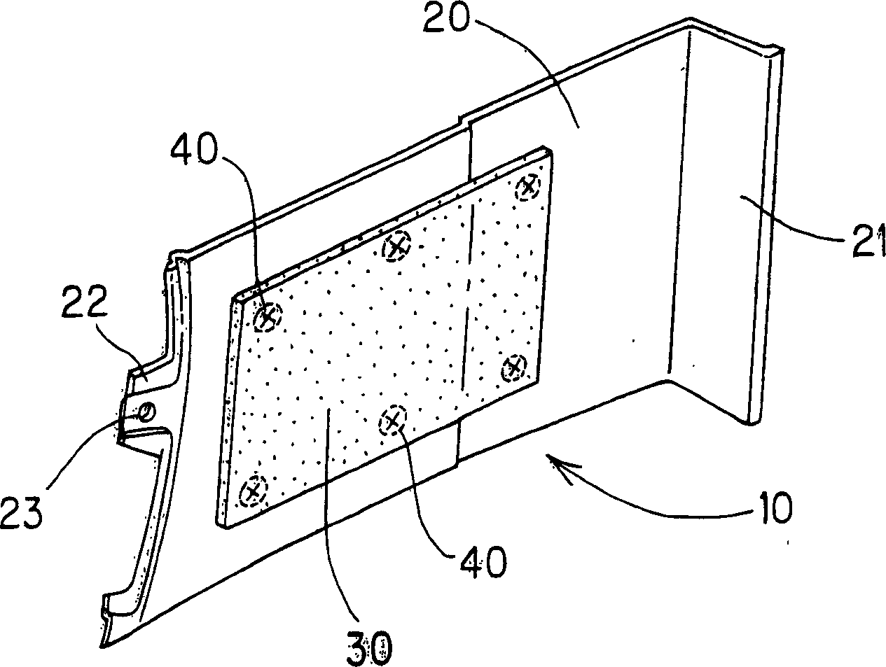
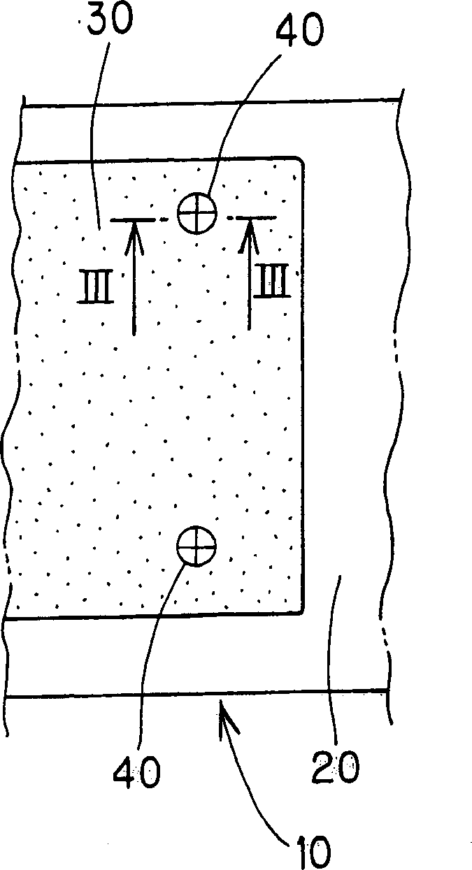
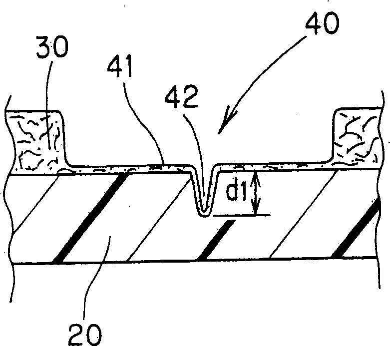
[0031] figure 1 ~ Fig. 5 is the accompanying drawing that shows the first embodiment of the present invention, figure 1 It is a perspective view showing the luggage side trim with the non-woven fabric cover bonded to the inside seen from the inside side of the luggage; figure 2 is a front view showing the non-woven fabric cover bonded to the main body of the luggage side trim; image 3 It is a sectional view showing the structure of the welded portion of the above-mentioned nonwoven fabric cover; Fig. 4 shows the shape of the ultrasonic horn used in the first embodiment, wherein (a) is a front view of the ultrasonic horn, and (b) is (a) A view; FIG. 5 is a cross-sectional view showing the welding process of the fibrous cover using the ultrasonic horn shown in FIG. 4; FIGS. 6 to 9 show each modification of the first embodiment Illustrating.

[0032] figure 1 Among them, 10 denotes a luggage side trim mounted on the interior surface of a side wall panel in the trunk of a...

Embodiment 2

[0045] Figure 10. Figure 11 Fig. 10 is an explanatory diagram showing the structure of an ultrasonic horn whose shape is changed, Fig. 10 (a) is a front view of the ultrasonic horn, Fig. 10 (b) ) is the D-direction view in (a). and Figure 11 It is an explanatory view showing the welded portion of the non-woven fabric cover formed by the ultrasonic horn shown in FIG. 10 . In the ultrasonic horn 50C shown in FIG. 10 , on the flat pressing surface 51 at the front end of the horn, a sharp ridge 52 is provided around the periphery of the pressing surface 51 . Since the ultrasonic horn 50C has a structure in which the ridges 52 are formed on the flat pressing surface 51 along the peripheral edge, it is necessary to use an NC lathe in the first embodiment. In the second embodiment, only a lathe is used. Therefore, the processing cost of the ultrasonic horn 50C can be reduced.

[0046] Furthermore, in the case of using the ultrasonic horn 50C, such as Figure 11 As shown, if th...


PUM


Abstract

The invention relates to a fixing structure of fiber cover to integrate the cover fiber as non-woven cover and the resin molded product, which will not generate surface defects as convex-concave on the surface of resin molded product, and it can reduce the processing time and simplifying the processing device. Wherein, the decoration (10) on the side of luggage case is processed by melting the fiber cover as non-woven cover (30) and the inner surface of decoration (20). It uses the sharp convex rib (52) on the processing surface (51) of ultrasonic horn (50) to form the melting part (4) of non-woven cover (3) on the plane melting surface (41) to inserted into the V-shape groove (42) inside the resin molded product. The invention can simply inserted the fiber of non-woven cover (30) into resin molded product (20) to generate fixing effect and form the V-shape groove (42) of resin molded product in short time to improve the operation availability and appearance.

Description

technical field [0001] The present invention relates to a fixing structure of a fibrous covering, especially when the fibrous covering is integrated with a resin molding made of a thermoplastic resin by ultrasonic welding, a strong joint strength can be obtained by welding in a short time The fixed structure of the fibrous overlay. Background technique [0002] Generally, interior trims made of resin moldings are mounted on the interior surface side of vehicle body panels with mounting mechanisms such as clips, and on the vehicle body panel surface side of these interior trims, such as Figure 12 As shown, the sound-absorbing member 2 is bonded and fixed to the inner surface of the interior trim 1 by means of an adhesive 3, and the sound-absorbing member 2 prevents noise from outside the vehicle from being transmitted into the vehicle interior, thereby forming a structure that can improve the quietness of the vehicle interior. [0003] Since this interior decoration 1 can be...

Claims


Application Information

Patent Timeline
Patent Type & Authority Applications(China)
IPC IPC(8): B32B27/12
CPCB29C66/81433B29C65/08B29C66/8322B29C66/21B29C66/71B29C66/73921
Inventor 佐佐木圭
Owner KASAI KOGYO CO LTD
Why Eureka
Try Eureka