Parallel connection LED drive circuit with adaptive mode switching

A technology of LED driving and mode switching, applied in the direction of electric lamp circuit layout, electric light source, lighting device, etc., can solve the problem of efficiency loss, not taking into account the LED conduction voltage drop, etc., achieve high conversion efficiency, achieve soft start and overtime The effect of pressure protection and strong implementability

Inactive Publication Date: 2006-07-12
CHIPHOMER TECH SHANGHAI
View PDF0 Cites 13 Cited by
  • Summary
  • Abstract
  • Description
  • Claims
  • Application Information

AI Technical Summary

Problems solved by technology

[0023] Usually V OUT voltage is set above 4V, due to the V OUT voltage is limited, so the mode switching point V TH The actual conduction voltage drop of the LED is not considered, which will cause efficiency loss in different situations
For example, when V BATTERY = 4V, VLED = 3V, it can work in 1× mode and enter 1.5× mode, the loss of efficiency is obvious

Method used


Image

  • Parallel connection LED drive circuit with adaptive mode switching
  • Parallel connection LED drive circuit with adaptive mode switching
  • Parallel connection LED drive circuit with adaptive mode switching

Examples


Embodiment Construction

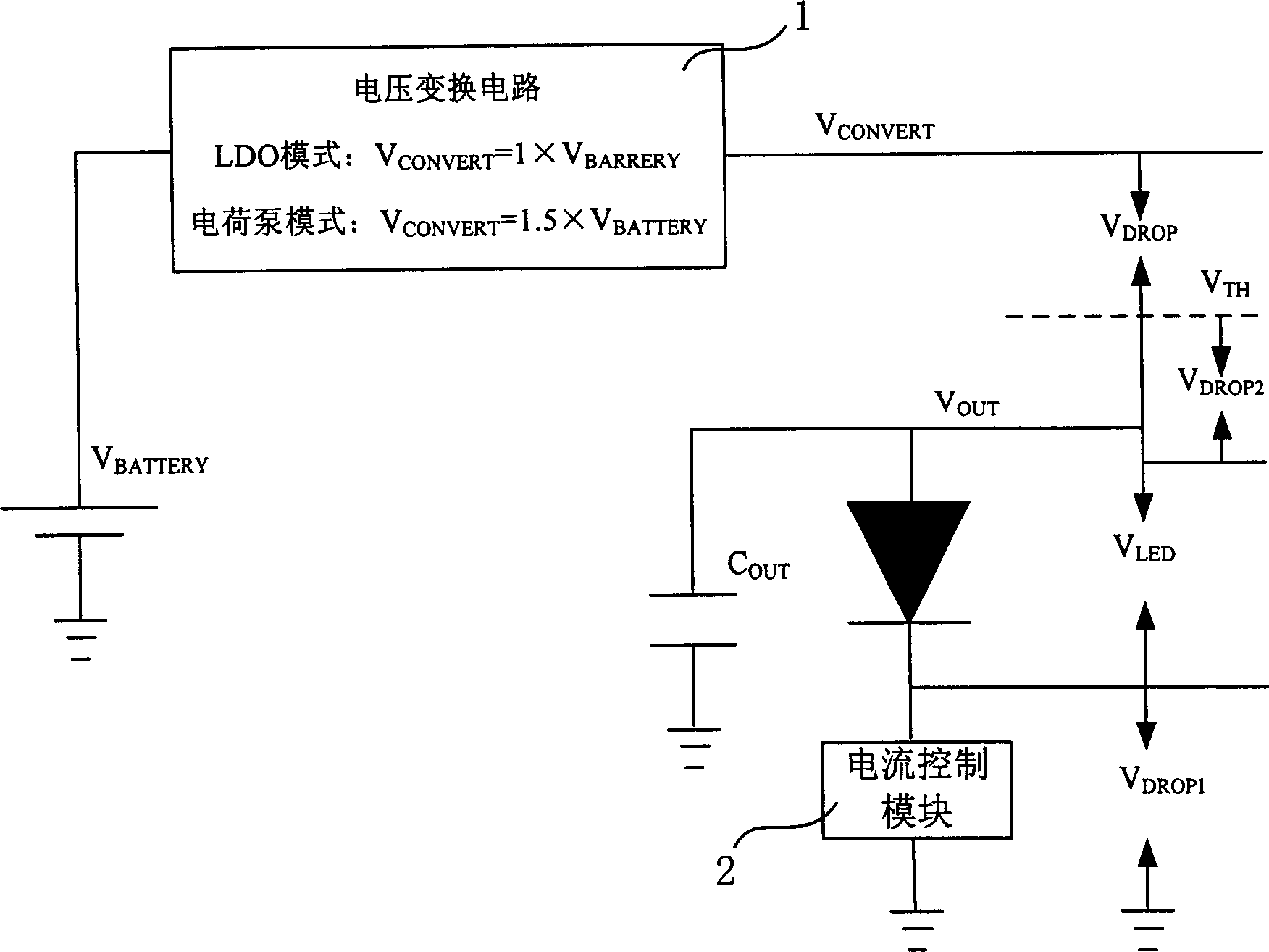
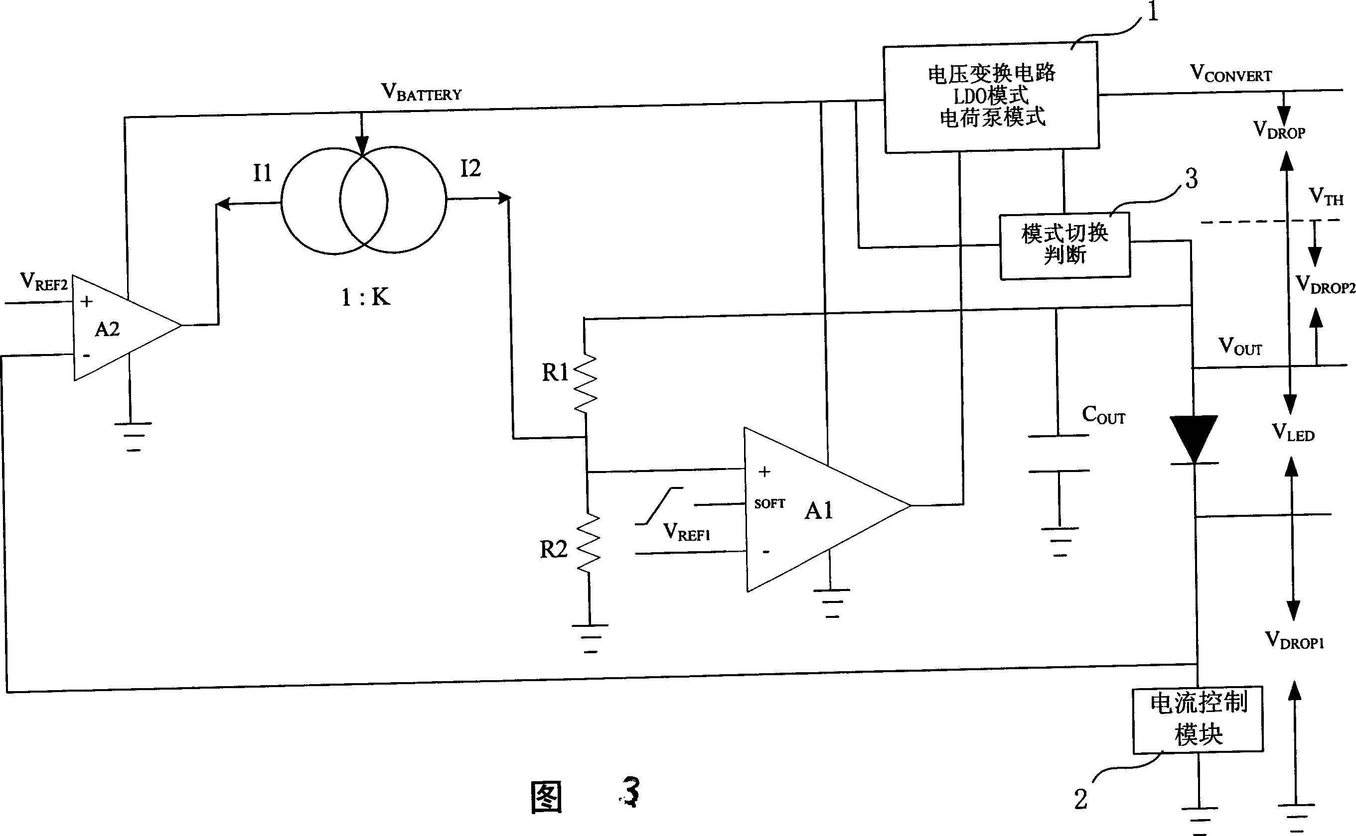
[0036] As shown in Figure 3, in the circuit of the present invention, V DROP1 The voltage is set to a fixed, relatively small voltage value, generally between 200-400mV, so V OUT Voltage is no longer a fixed voltage value. According to Equation 1, the mode switching voltage V TH It is no longer a fixed voltage, but will be adjusted according to the forward voltage drop of the LED.

[0037] According to the mode switching criterion given in Equation 2, it can be seen that: through the mode switching voltage V TH According to the adaptive change of the load LED characteristics, the adaptive control of mode switching is realized.

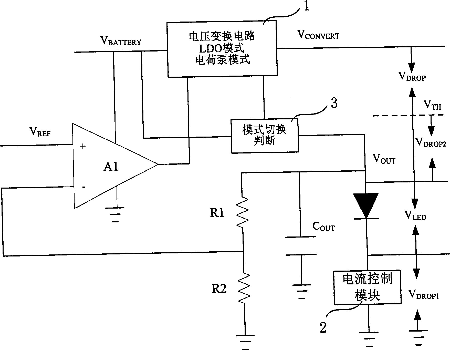
[0038] As shown in Figure 3, the present invention, that is, a parallel LED drive circuit with adaptive mode switching, includes a voltage conversion circuit 1, a mode switching judgment circuit 3, a current control module 2, an operational amplifier A1, and voltage dividing resistors R1 and R2 , capacitance C out , and a feedback control loop, wh...


PUM


Abstract

Disclosed is a parallel LED driving circuit with self-adapting switching mode which comprises: current control module; operation amplifier (A1); resistors (R1, R2); a feedback control loop which includes a second operation amplifier (A2) and current mirrors (I1, I2) connected with A2. The invention is characterized in that: the voltage difference that is amplified by A2 between voltage (VDROP1) and reference voltage (VREF2) on the current control module controls the current of current mirror (I2) that flows through the resistor (R2); voltage on R2 is amplified by amplifier (A1) and fed back to the negative terminal of the second amplifier (A2) to ensure the voltage value (VDROP1) equals the reference voltage value (VREF2).

Description

technical field [0001] The invention relates to an analog integrated circuit, in particular to a parallel drive circuit with adaptive mode switching. Background technique [0002] In the backlight drive circuits of handheld devices such as mobile phones and MP3 players, a lithium battery is usually used to power the entire system, and the voltage of the lithium battery is generally between 3.6V and 4.2V. The threshold voltage of different types of white LEDs (light-emitting diodes) varies greatly, and at the same time changes with changes in temperature and driving current. Generally, the forward conduction voltage drop of LEDs V LED Probably in the 2.5V-4.5V range. Therefore, for LEDs with a large conduction voltage drop, it is necessary to convert the lithium battery voltage to a higher voltage to provide sufficient driving capability. [0003] According to the voltage conversion method, the drive circuit can generally be divided into two types, one is series drive, base...

Claims


Application Information

Patent Timeline
Patent Type & Authority Applications(China)
IPC IPC(8): G09G3/34H05B37/02
Inventor 孙洪军余兴智
Owner CHIPHOMER TECH SHANGHAI
Why Eureka
Try Eureka