Electrophoretic dipping system

A dip coating and equipment technology, applied in electrolytic coatings, electrophoretic plating, coatings, etc., can solve the problems of damage to the durability of the dialysis unit, expensive and heavy smooth choke coils, etc., to improve the coating effect, prevent The effect of electrostatic field entering the interior

Inactive Publication Date: 2006-07-12
EISENMANN MASCHINENBAU GMBH & CO KG
View PDF0 Cites 4 Cited by
  • Summary
  • Abstract
  • Description
  • Claims
  • Application Information

AI Technical Summary

Problems solved by technology

The smoothing elements required to smooth this voltage require very large smoothing chokes, which are not only expensive but also heavy and take up a lot of space
Despite the use of such expensive smoothing elements, in known cationic electrophoretic dip coating installations there remains a non-negligible residual ripple in the voltage between the anode and the object to be coated, which is detrimental to the final coating obtained influences
Also impairs the durability of the dialysis unit that is typically placed around the anode in a dipping tank
Additionally, the cosφ of these known power supply units is small

Method used


Image

  • Electrophoretic dipping system
  • Electrophoretic dipping system
  • Electrophoretic dipping system

Examples


Embodiment Construction

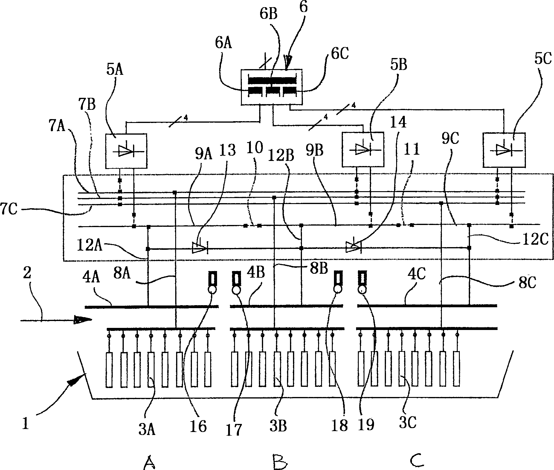
[0025] First refer to figure 1 . In this figure, reference numeral 1 indicates a dipping tank, which is filled with liquid paint during operation. The object to be painted, for example a motor vehicle body, is immersed in this dipping bath 1 . This can be done in a continuous pass method, in which the objects to be coated are mounted on a conveyor which moves the objects into, through and out of the dip coating tank 1 . Alternatively, however, the object can also be coated in the dipping tank 1 by the takt-Tauchverfahren method. For the purposes of the following description, a continuous pass method is assumed; the direction of movement of the object to be painted is indicated by arrow 2 .

[0026] For depositing paint particles, such as pigments, binders and filler particles, contained in a liquid paint, the surface of the object is brought to the cathodic potential of an electric field established between a plurality of anodes 3 and the surface of the object as it passes ...


PUM


Abstract

The invention relates to an electrophoretic dipping system comprising at least one dipping bowl (1) which can be filled with a liquid and an object which is to be coated and which can be dipped therein. At least one power supply unit (5A, 5B, 5C) produces DC voltage with definite residual ripple from AC voltage. The one pole thereof can be connected to at least one electrode of a first polarity (3A, 3B, 3C), said electrode being arranged in the dipping bowl (1) and the other pole thereof can be connected to the object which is to be coated. The power supply unit (5A, 5B, 5C) comprises one uncontrolled diode rectifier bridge (19) and an IGBT switch (22) which comprises a controllable oscillator (24) and a power transistor (23). The controllable oscillator (24) generates pulses having a repetition frequency ranging from between 5 and 30 kHz with variable pulse widths. The power transistor (23) is controlled by said pulses. The voltage pulses produced therefrom can be smoothed out with the aid of relatively small smoothing elements until a highly reduced residual ripple which benefits the quality, especially the smoothness and the roughness of the applied protective coating is obtained. Said power supply unit (5A, 5B, 5C) also has a highly improved cos Phi compared to currently known thyristor bridge switches used for the same purpose.

Description

technical field [0001] The present invention relates to a kind of electrophoretic dip coating equipment, comprising: [0002] a) at least one dipping tank, which can be filled with a paint solution and into which the object to be coated can be immersed; [0003] b) at least one electrode having a first polarity and disposed in said dipping tank; [0004] c) at least one power supply unit which generates from an alternating voltage a direct voltage with a defined residual ripple, one pole of which is connectable to said electrode with the first polarity and the other pole of which is connectable to the electrode to be painted object, and the power supply unit has smoothing elements for reducing residual ripple. Background technique [0005] Such electrophoretic, usually cationic electrophoretic dip coating systems are known on the market. Such dipping equipment must be able to supply a smoothed DC voltage with a variable voltage level to suit the given situation. Only in ...

Claims


Application Information

Patent Timeline
Patent Type & Authority Applications(China)
IPC IPC(8): C25D13/22C25D13/18H02M1/08H02M7/217
CPCH02M1/083H02M7/217C25D13/22C25D13/18
Inventor H·K·范卡普亨斯特W·马伊B·拉贝M·埃宾豪斯
Owner EISENMANN MASCHINENBAU GMBH & CO KG
Why Eureka
Try Eureka