Eureka AIR delivers breakthrough ideas for toughest innovation challenges, trusted by R&D personnel around the world.

Completely hydraulically driven breaking dredger

A traveling, fully hydraulic technology, applied in the direction of solid separation, filter screen, grille, etc., can solve the problems that the dumper cannot unload coal normally, the machine cannot be returned to the machine room, and can only stop on the coal grate, etc., reaching the weight Lightweight, smooth running, and less maintenance work

Inactive Publication Date: 2006-07-19
长沙通发高新技术开发有限公司
View PDF0 Cites 13 Cited by
  • Summary
  • Abstract
  • Description
  • Claims
  • Application Information

AI Technical Summary

Problems solved by technology

Therefore, the travel force of the equipment is limited, and when the equipment encounters a slightly larger resistance, it is very easy to slip
The running mechanism of all existing domestic similar equipment relies on the rolling friction between the steel wheel (including two-wheel drive or four-wheel drive) and the steel rail, which is very easy to slip, especially when there is water, mud or wet on the rail surface. When the coal and the resistance to travel are slightly greater, slippage occurs. At this time, the machine can only stop on the coal grate, and cannot advance or retreat, and the dumper cannot unload coal normally.
None of the existing domestic equipment is equipped with a hand-operated device. When the machine slips or stops or the electrical appliances fail, the machine cannot be returned to the machine room, which affects the unloading operation.

Method used

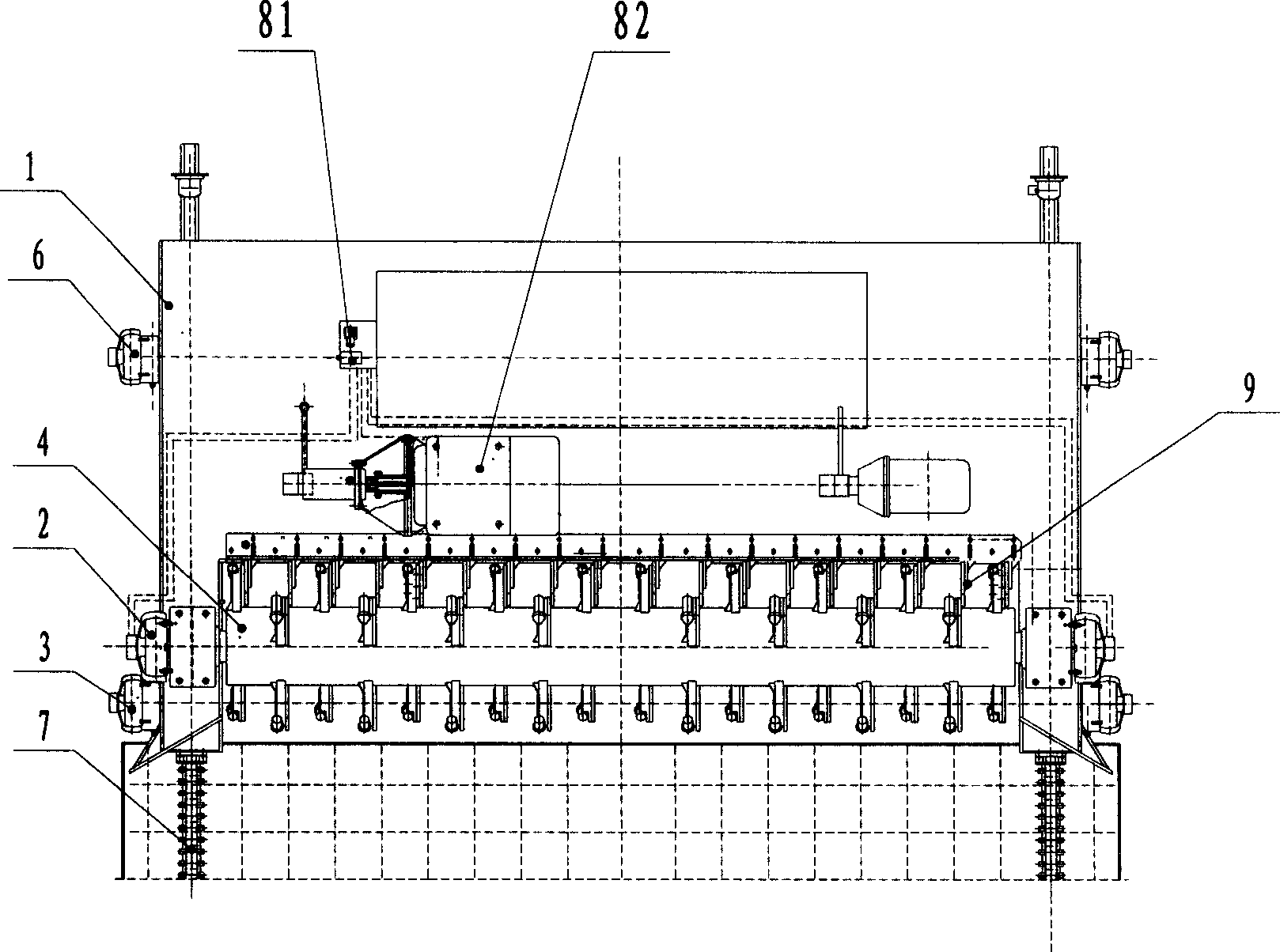
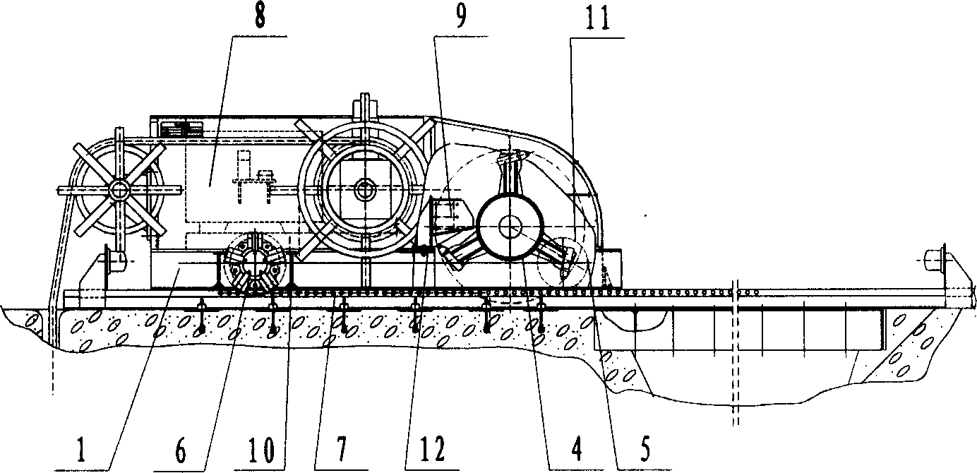
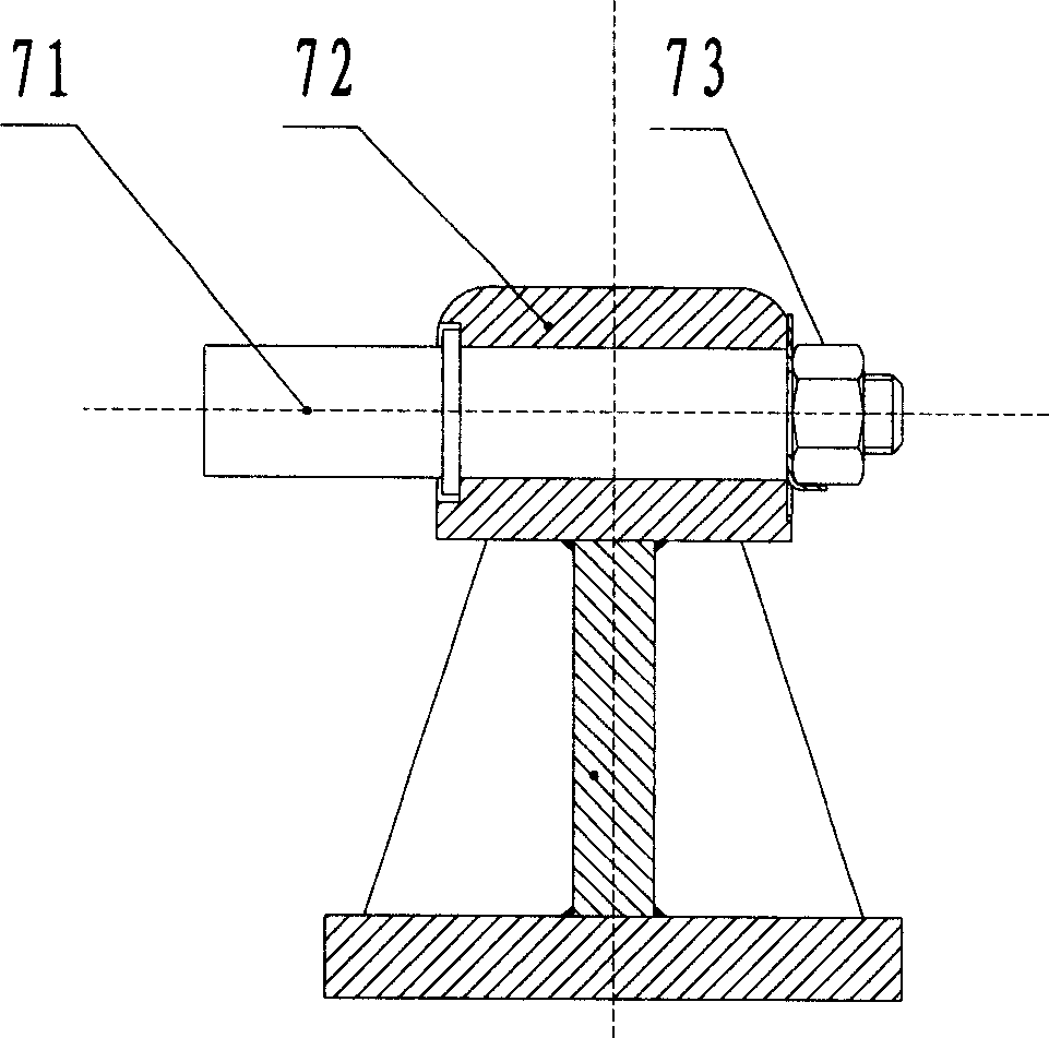

Image

  • Completely hydraulically driven breaking dredger
  • Completely hydraulically driven breaking dredger
  • Completely hydraulically driven breaking dredger

Examples


Embodiment Construction

[0037] The present invention will be described in further detail below in conjunction with the accompanying drawings and specific embodiments.

[0038] Such as figure 1 and figure 2 As shown, the full-hydraulic driven traveling shredder of the present invention includes a crushing roller 4, a crushing roller transmission mechanism 2, a traveling transmission mechanism 3, a traveling device 5, a hydraulic control system 8, a frame 1 and a track 7. The crushing roller transmission mechanism 2 and the traveling transmission mechanism 3 are arranged on the frame 1, the traveling device 5 includes the front wheel 11 and the rear wheel 6 which are arranged on the bottom of the frame 1 and supported on the track 7, and the crushing roller 4 is supported on the frame 1 on both sides. The hydraulic control system 8 is fixed on the frame 1, and it includes a crushing roller hydraulic control system 81 and a walking hydraulic control system 82. The traveling device 5 is connected to ...


PUM


Abstract

The invention discloses an all-hydraulic driving traveling grinding cleaner, which comprises the following parts: bruising roll, bruising roll driving structure, walking driving structure, walking device, hydraulic control system, rack and rail, wherein the bruising driving structure and walking driving structure are set on the rack; the walking device contains front wheel and back wheel; the bruising roll is supported on two sides of rack; the hydraulic control system is fixed on the rack, which contains bruising roll hydraulic control system and walking hydraulic control system; the walking device connects the walking hydraulic control system through walking driving structure; the walking driving structure contains walking hydraulic motor and driving shaft; the walking hydraulic motor connects the walking device through driving shaft; the bruising roll connects the bruising roll hydraulic control system through bruising roll driving structure; the bruising roll driving structure contains two bruising roll hydraulic motor on two ends of bruising roll; the bruising roll hydraulic motor connects the bruising roll through coupler.

Description

technical field [0001] The invention mainly relates to a coal grate under the train coal dumper and a coal grate on the coal pit or other grates on the hopper in the coal unloading room of the car. Shuji. Background technique [0002] In enterprises that use a large amount of coal (or other bulk materials) in industries such as electric power and metallurgy, usually, coal transported into the plant by train or automobile must be screened for the first time through coal grates. In the past, the sundries remaining on the coal grate after screening, such as large pieces of coal, coal gangue, straw ropes, woven bags, etc., were all handled manually. With the development and progress of society, manual cleaning in such a harsh environment can no longer meet the requirements, efficiency and pace of modern production, and manual operation will be replaced by high-efficiency machinery and equipment. As a result, various types of dredgers have emerged. [0003] At present, the dre...

Claims


Application Information

Patent Timeline
Patent Type & Authority Applications(China)
IPC IPC(8): B07B1/50
Inventor 阎国俊谢泳清肖刚军刘新民
Owner 长沙通发高新技术开发有限公司
Why Eureka
Eureka Blog
Learn More