


Quick Research
Generate reliable direction feasibility study reports for your R&D in just a few steps.

Technical Q&A
Discover and master advanced knowledge NOW. Basics, ideas, possibilities, all at once.

Find Solutions
As an expert in R&D theories, this can generate solutions to your technical problems instantly.

Evaluate Feasibility
Analyze your overall solution with one click, know your potential R&D risks in advance.

Monitor Landscape
Get weekly tech updates, stay abreast of the latest tech innovations and key insights.
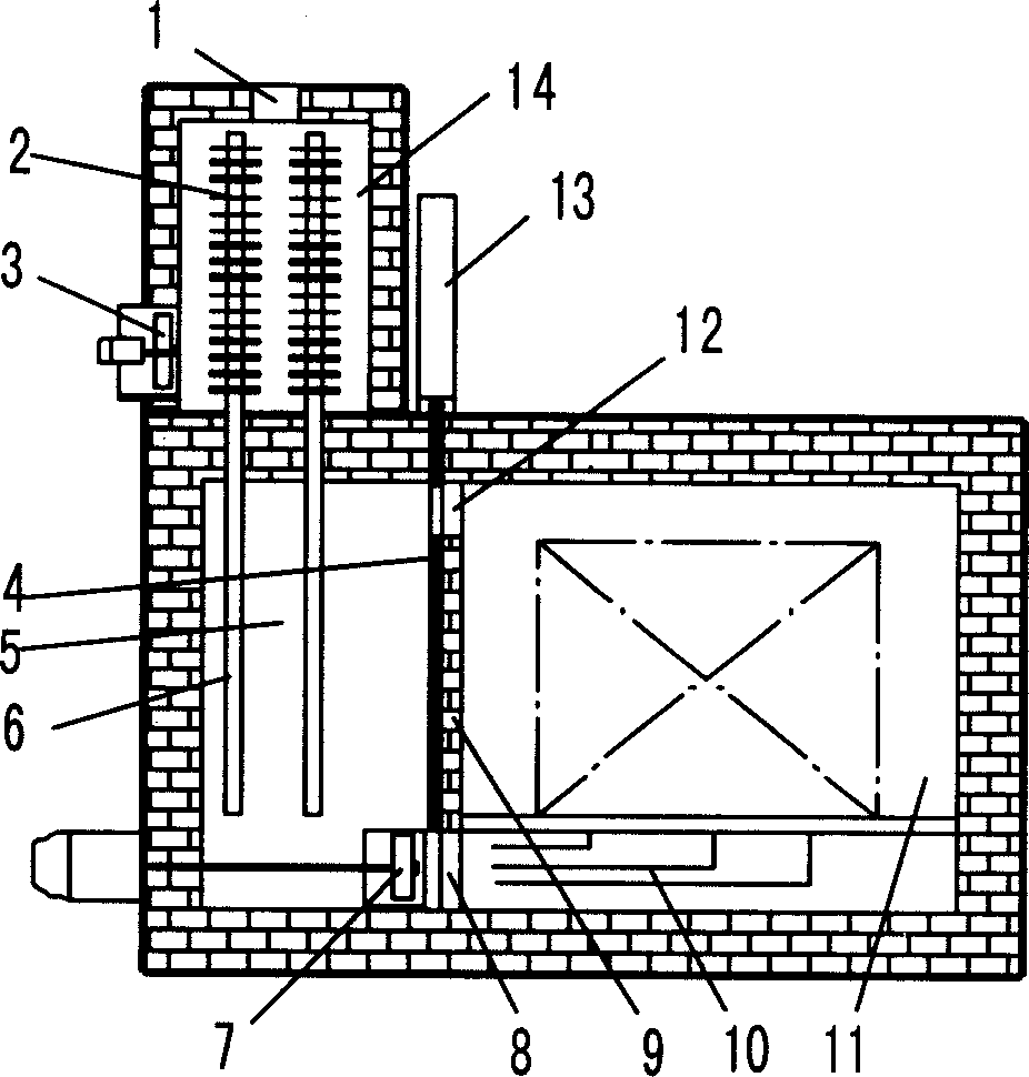
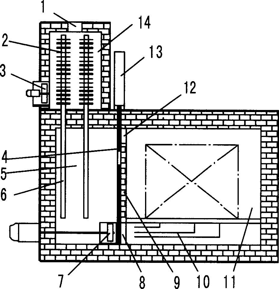
Heat treatment furnace employing heat pipe to quickly lower temperature
A heat treatment furnace and heat pipe technology, applied in heat treatment furnaces, heat treatment equipment, furnaces, etc., can solve problems such as heat removal, achieve high heat exchange efficiency, and avoid large water consumption.
- Summary
- Abstract
- Description
- Claims
- Application Information
AI Technical Summary
Problems solved by technology
Method used
Image

Examples
Embodiment Construction
[0010] Such as figure 1 As shown, the present invention includes: hot air outlet 1, heat pipe heat dissipation end 2, cold air fan 3, windshield 4, heat exchange chamber 5, heat pipe heat absorption end 6, heat circulation fan 7, lower vent 8, heat insulation wall 9 , wind deflector 10, heating chamber 11, upper air vent 12, power push rod 13, cooling chamber 14, its connection mode is: the heat-absorbing end 6 of the heat pipe is installed in the heat exchange chamber 5, and the radiating end 2 of the heat pipe is installed in the cooling chamber 14, a cold air blower 3 is installed at the bottom of the cooling chamber 14, a hot air outlet 1 is set on the top of the cooling chamber 14, a heat insulating wall 9 is set between the heat exchange chamber 5 and the heating chamber 11, and a heat insulating wall 9 is provided on the heat insulating wall 9. The lower ventilation opening 8 and the upper ventilation opening 12 are provided with a windshield 4 adjacent to the heat insu...
PUM
 Abstract
Description
Claims
Application Information
 - R&D Engineer
- R&D Manager
- IP Professional
- Industry Leading Data Capabilities
- Powerful AI technology
- Patent DNA Extraction
Browse by: Latest US Patents, China's latest patents, Technical Efficacy Thesaurus, Application Domain, Technology Topic, Popular Technical Reports.
© 2024 PatSnap. All rights reserved.Legal|Privacy policy|Modern Slavery Act Transparency Statement|Sitemap|About US| Contact US: help@patsnap.com