Projection soldering structure of power head part for thermal expansion valve

A thermal expansion valve and power head technology, applied in the field of thermal expansion valves, can solve problems such as difficulty in one-time realization of the process, increased welding energy, internal corrosion, etc., and achieve the effects of ensuring sealing, preventing outer wall corrosion, and avoiding unreliability

Active Publication Date: 2006-08-09
ZHEJIANG SANHUA AUTOMOTIVE COMPONENTS CO LTD
View PDF2 Cites 9 Cited by
  • Summary
  • Abstract
  • Description
  • Claims
  • Application Information

AI Technical Summary

Problems solved by technology

However, since the projection welding is directly connected together by melting the contact parts of two connected parts through resistance heat, the smaller the contact area of ​​the two parts, the greater the resistance heat generated per unit area, and the better the welding effect. The opposite is the opposite; therefore, the above solution sacrifices the welding quality per unit area while achieving multiple welding positions, which is undesirable to seal the heat-sensitive medium in the containing chamber with a plug, unless the welding energy is increased ; Moreover, the "cavity" pointed out in the CN 1058779C No. invention patent description will be formed between multiple welding positions to cause internal corrosion problems
[0004] On a deeper level, due to the heat expansion of the sealed heat-sensitive medium during welding, the pressure increases, which is very unfavorable for the relatively small welding part (0.2-1.5mm) formed by projection welding; based on the characteristics of projection welding, It is unavoidable to form a concave part around the convex welding part, so in order to prevent the outer wall from corrosion, it is difficult to realize it in one process by covering the surrounding of the convex welding part with anti-corrosion material

Method used


Image

  • Projection soldering structure of power head part for thermal expansion valve
  • Projection soldering structure of power head part for thermal expansion valve
  • Projection soldering structure of power head part for thermal expansion valve

Examples


Embodiment 1

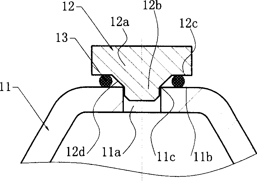
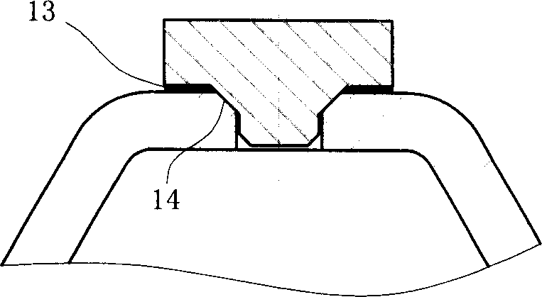
[0019] Such as Figure 1a , 1b As shown, a round hole 11a is set on the outer wall 11 as a filling hole, and the position adjacent to the round hole 11a on its upper surface forms a plane as the outer wall brazing surface 11b, and the upper edge of the hole wall of the round hole 11a is the outer wall convex welding portion 11c; The plug 12 is in the form of a truncated cone, with its upper end as a cylindrical tail 12a and its lower end as a truncated cone head 12b. The side of the truncated cone head 12b forms a theoretical line contact with the projection welding portion 11c to form a plug projection welding portion 12d. The step surface adjacent to the head and the tail is the brazing surface 12c; the solder 13 is placed between the outer wall brazing surface 11b and the plug brazing surface 12c; The clamp clamps the tail of the plug and pushes it into the filling hole and presses it tightly (the head of the plug cooperates with the filling hole to have a guiding effect), ...

Embodiment 2

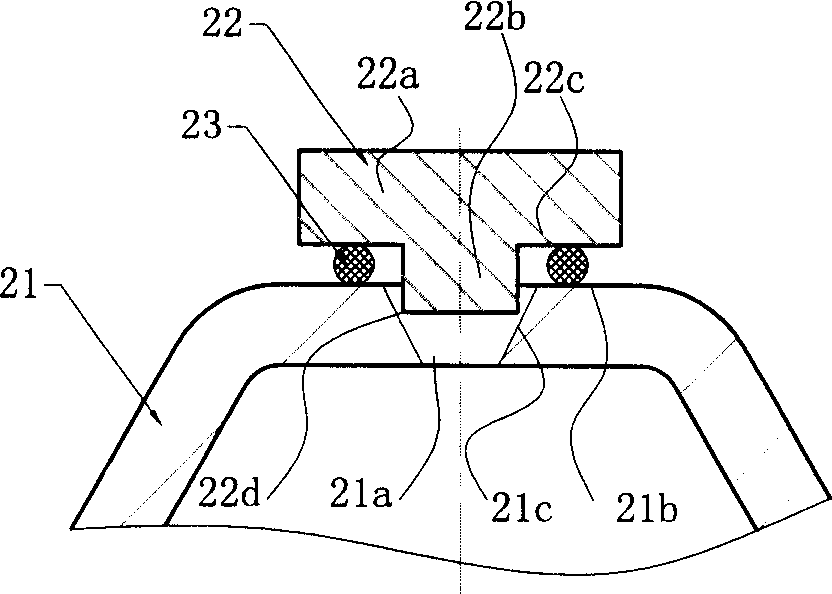
[0021] Such as Figure 2a , 2b As shown, a taper hole 21a is set on the outer wall 21 as a filling hole, and the position adjacent to the taper hole 21a on its upper surface forms a plane as the outer wall brazing surface 21b, and the side wall of the taper hole 21a forms a theoretical gap with the head of the plug. line contact to form the outer wall convex welding portion 22c; the plug 22 is in the shape of a circular platform, the upper cylindrical portion is used as the tail portion 22a, the lower cylindrical portion is used as the head portion 22b, and the step surface adjacent to the head portion and the tail portion is a brazing surface 22c. The peripheral edge of the head 22b is the plug projection welding portion 22d corresponding to the outer wall projection welding portion 12c; the brazing material 23 is placed between the outer wall brazing surface 21b and the plug brazing surface 22c; the welding method is the same as that of the first embodiment, 24 in the figure...

Embodiment 3

[0023] Such as Figure 3a , 3b As shown, a variable-diameter hole 31a is set on the outer wall 31 as a filling hole. The upper section of the variable-diameter hole is a tapered hole, and the lower section is an equal-diameter hole. The upper surface of the outer wall adjacent to the tapered hole forms a plane as the outer wall brazing surface 31b. , the side wall of the taper hole forms a theoretical line contact with the head of the plug to form an outer wall projection weld 32c; The step surface adjacent to the head portion and the tail portion is a brazing surface 32c, and the peripheral edge of the head portion 32b is a plug projection welding portion 32d corresponding to the outer wall projection welding portion 32c; brazing material 33 is placed on the outer wall brazing surface 31b and the plug brazing surface Between 32c; Welding method is the same as embodiment one, and 34 among the figure is projection welding sealing.


PUM


Abstract

The invention relates to a convex brazing structure of dynamic head component of thermal expansion valve. The dynamic head component is consists of a stopper and a cavity which used to accommodate the thermal-sensitive medium. The cavity has holes in its ektexine and the medium can be added into the cavity through the holes. The stopper is used to plug the holes so the medium is sealed in the cavity. Its characteristics are implementing convex brazing between the stopper and the holes to form the first part of welding line, placing brazing filler metal between the stopper and the ektexine and brazing to form the second part of welding line. The welding field is formed in one time, and at the time of the completion of the first part of seal, the solder is prevented from flowing into the cavity when the brazing filler metal is melted. The seal and the antisepsis are mainly realized by the brazing.

Description

【Technical field】 [0001] The invention relates to a thermal expansion valve suitable for an air-conditioning system, especially a structure for sealing a heat-sensitive medium in an accommodating cavity by sealing a filling hole of a power head (also called an air box head) with a plug. 【Background technique】 [0002] The existing thermal expansion valve suitable for air-conditioning systems is clearly recorded in the invention patent specification with the notification number CN 1058779C. The structure in the cavity is described in detail, and the analysis and induction of the prior art in this document are as follows: ①Project welding is performed between the edge around the hole and the conical surface of the plug, because a concave part is formed around the convex welding part, so Water accumulation (condensation water, etc.) is likely to occur in the concave part, and there is a problem of corroding the outer wall of the cover; ② The plug is tack welded by projection we...

Claims


Application Information

Patent Timeline
Patent Type & Authority Applications(China)
IPC IPC(8): B23K33/00
Inventor 杜又德
Owner ZHEJIANG SANHUA AUTOMOTIVE COMPONENTS CO LTD
Why Eureka
Try Eureka