Compensation-type spiral micro-band resonance unit and annular coupler formed thereby

A microstrip resonant unit and coupler technology, applied in the field of ring couplers and microwave ring couplers, can solve the problems of passive filter loss, mismatch, and not very ideal structure, and achieve small insertion loss and reduce The effect of circuit area

Inactive Publication Date: 2006-08-09
SHANGHAI INST OF MICROSYSTEM & INFORMATION TECH CHINESE ACAD OF SCI
View PDF0 Cites 5 Cited by
  • Summary
  • Abstract
  • Description
  • Claims
  • Application Information

AI Technical Summary

Problems solved by technology

The usual microwave communication system is to add a low-pass filter or a band-pass filter inside the system to achieve the purpose of suppressing harmonics. differential loss, reducing system performance
And when the internal components of the system are interconnected, there may be a mismatch and deteriorate the system performance
Especially in the low-frequency band, the shape of the ring line coupler is too large, and the substrate space cannot be used very effectively, so this structure is not very ideal

Method used


Image

  • Compensation-type spiral micro-band resonance unit and annular coupler formed thereby
  • Compensation-type spiral micro-band resonance unit and annular coupler formed thereby
  • Compensation-type spiral micro-band resonance unit and annular coupler formed thereby

Examples


Embodiment Construction

[0019] The substantive features and remarkable progress of the present invention will be further elaborated below through the embodiments and in conjunction with the accompanying drawings.

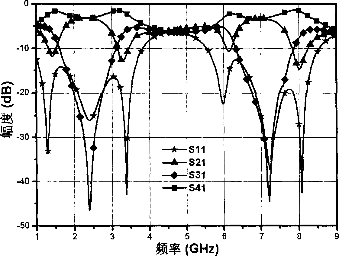
[0020] image 3 It shows a helical microstrip resonant unit published by Xue Quan in 2000. The resonant unit is composed of four helical microstrip open lines in a 50Ω microstrip transmission line. The forbidden band is generated through resonance, thereby playing the role of filtering. In addition, at the same time It increases the distributed capacitance and inductance of the transmission line, which has the effect of slow wave. Figure 4 It is the frequency response curve of the spiral microstrip resonant unit with a characteristic impedance of 50Ω, where the solid line is the simulation curve and the dotted line is the test curve. from Figure 4 It can be seen from the frequency response curve that in the spiral microstrip resonant unit, in order to achieve the required slow wave and...


PUM


Abstract

Compensation type microstrip resonance unit consists of four pieces of microstrip open-circuit line in helicoid form. There are two pieces of compensation structures of microstrip open-circuit line with one in long annulus form and the other in short annulus form. Annular coupler includes six pieces of compensation type microstrip resonance unit in helicoid form instead of traditional microstrip line in 1/4 wavelength. Microstrip open-circuit lines with long annulus form and in short annulus form are located inside annular coupler. Resonance unit is as a transmission line at fundamental frequency, and possesses strong inhibiting effect at harmonic second order and third-order. The disclosed annular coupler possesses advantages of inhibiting harmonic, reducing area of circuit, and small insertion loss.

Description

technical field [0001] The invention relates to a microwave ring coupler, in particular to a compensation type spiral microstrip resonant unit and the ring coupler formed thereof, and belongs to the field of microwave ring couplers. Background technique [0002] Theoretically speaking, the output power distribution ratio of the two output ports of the ring coupler can be arbitrary. But in reality, due to the limitations of the process, it is difficult to realize the ring coupler with a large difference in power distribution because the impedance of the part is too high. The most commonly used ring coupler in practice is -3 decibels (dB) with equal output power. [0003] figure 1 It shows the structural diagram of a traditional ring coupler. It can be seen from the figure that there are six microstrip lines with a characteristic impedance of 70.7Ω inside the coupler, and the length of each microstrip line is 1 / 4 of the operating frequency. one wavelength. Taking the workin...

Claims


Application Information

Patent Timeline
Patent Type & Authority Applications(China)
IPC IPC(8): H01P7/06H01P5/22
Inventor 顾建忠孙晓玮
Owner SHANGHAI INST OF MICROSYSTEM & INFORMATION TECH CHINESE ACAD OF SCI
Why Eureka
Try Eureka