High frequency winding assembly and magnetic resonance imaging apparatus

A magnetic resonance imaging, high-frequency coil technology, applied in magnetic resonance measurement, measurement device, material analysis through resonance, etc., can solve problems such as the distance between the outer surface coil and the spine becoming larger, the sensitivity cannot be obtained, and the imaging sensitivity cannot be achieved. , to achieve the effect of increasing the consultation rate and reducing the burden

Active Publication Date: 2006-08-16
TOSHIBA MEDICAL SYST CORP
View PDF2 Cites 8 Cited by
  • Summary
  • Abstract
  • Description
  • Claims
  • Application Information

AI Technical Summary

Problems solved by technology

[0015] However, when four identical surface coils are arranged in a direction intersecting with the body axis direction, the distance between the outer surface coil and the spine will increase, so sufficient sensitivity cannot be obtained in the end.
That is, although there are four surface coils, there is a possibility that the expected improvement in imaging sensitivity cannot be achieved.

Method used


Image

  • High frequency winding assembly and magnetic resonance imaging apparatus
  • High frequency winding assembly and magnetic resonance imaging apparatus
  • High frequency winding assembly and magnetic resonance imaging apparatus

Examples


no. 1 Embodiment

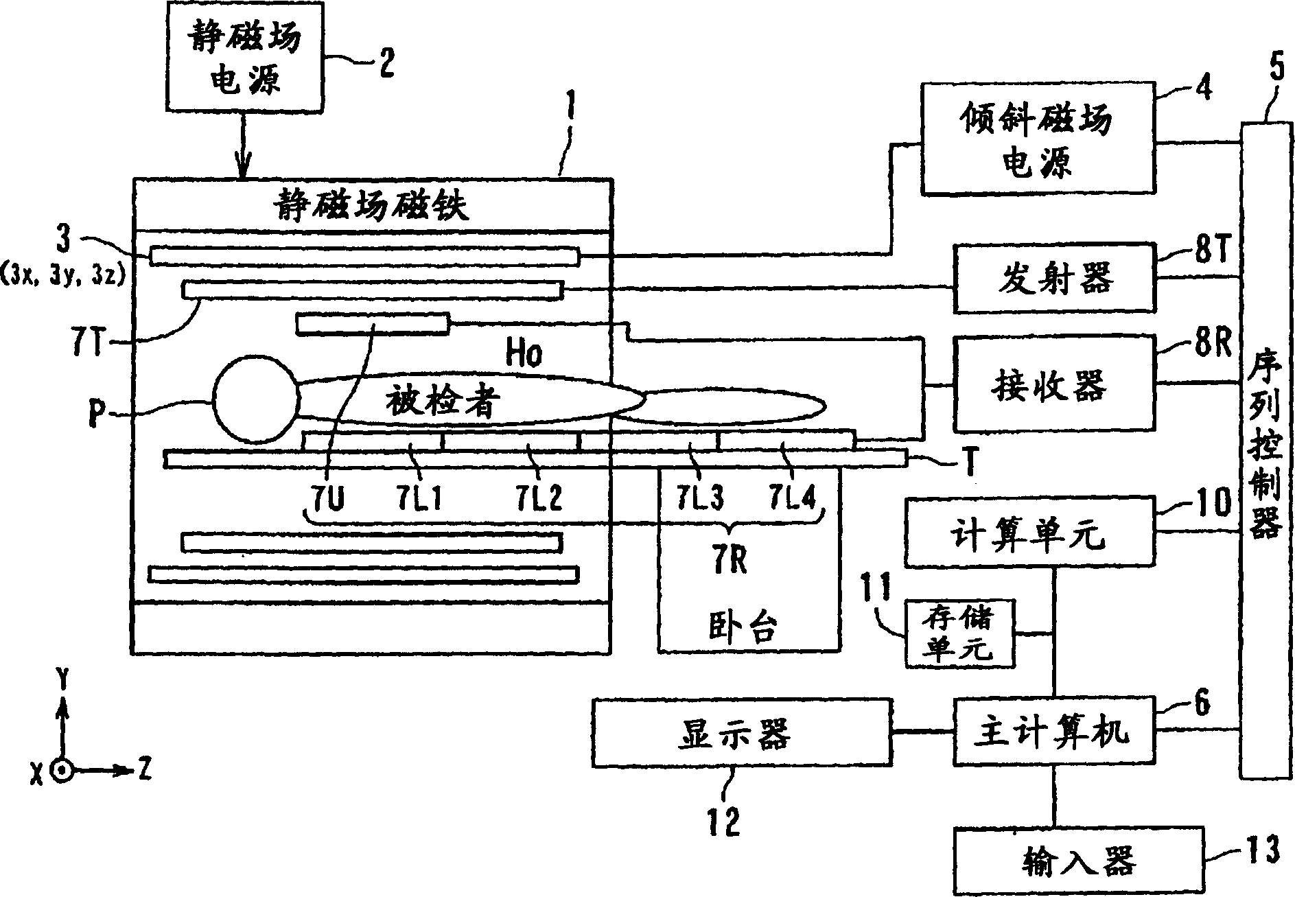
[0067] Refer below Figure 1-9 A magnetic resonance imaging apparatus according to a first embodiment of the present invention will be described.

[0068] figure 1 A schematic configuration of a magnetic resonance imaging (MRI: Magnetic Resonance Imaging) apparatus according to the first embodiment is shown.

[0069] This magnetic resonance imaging apparatus has a bed portion on which the subject P is placed, a static magnetic field generating portion generating a static magnetic field, a gradient magnetic field generating portion for adding position information to the static magnetic field, a transmitting and receiving portion for transmitting and receiving high-frequency signals, and a control system. The control and calculation unit of the overall and reconstructed image.

[0070] The static magnetic field generator includes, for example, a superconducting magnet 1 and a static magnetic field power supply 2 that supplies current to the magnet 1, and is positioned in the a...

no. 2 Embodiment

[0119] Figure 19 It is a diagram showing the configuration of the magnetic resonance imaging apparatus of the second embodiment.

[0120] The magnetic resonance imaging device has a static field magnet 101, a gradient magnetic field coil 102, a gradient magnetic field coil drive circuit 103, a bed 104, a transmitting unit 105, a transmitting high-frequency coil 106, a receiving high-frequency coil assembly 107, a receiving unit 108, Data collection unit 109 , computer 110 , sequence controller 111 , display 112 and console 113 .

[0121] The static magnetic field magnet 101 is in the shape of a hollow cylinder, and generates a uniform static magnetic field in the inner space. As the static field magnet 101, for example, a permanent magnet, a superconducting magnet, or the like is used. The gradient magnetic field coil 102 has a hollow cylindrical shape and is disposed inside the static field magnet 101 . The gradient magnetic field coil 102 is composed of three coils corre...

no. 3 Embodiment

[0148] Figure 24 It is a diagram showing the structure of the magnetic resonance imaging apparatus of the third embodiment. In addition, in Figure 24 In pair with Figure 19 The same symbols are used for the same parts, and detailed description thereof will be omitted.

[0149] The magnetic resonance imaging device has a static field magnet 101, a gradient magnetic field coil 102, a gradient magnetic field coil drive circuit 103, a bed 104, a transmitting unit 105, a transmitting high-frequency coil 106, a receiving unit 108, a data collection unit 109, a computer 110, Sequence controller 111 , display 112 , console 113 and receiving high-frequency coil assemblies 114 and 115 .

[0150] That is, the magnetic resonance imaging apparatus of the third embodiment has high-frequency coil units 114 and 115 instead of the high-frequency coil unit 107 of the second embodiment.

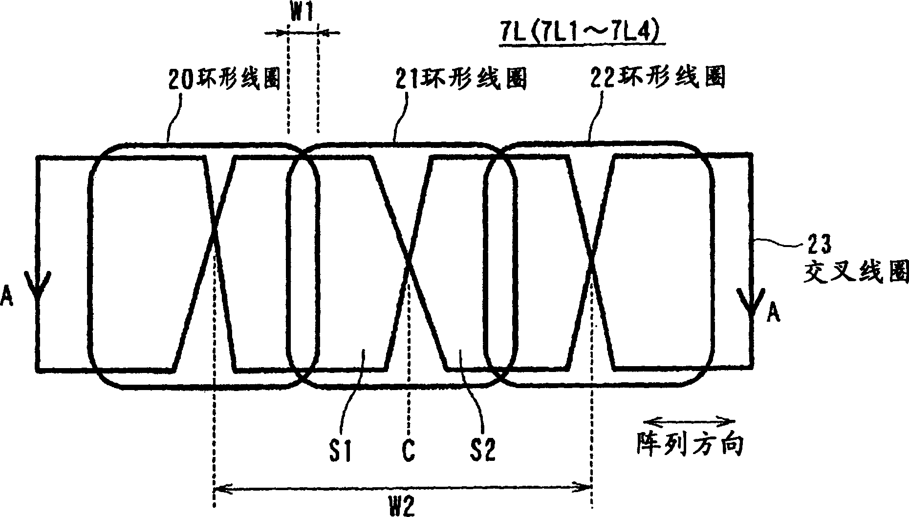
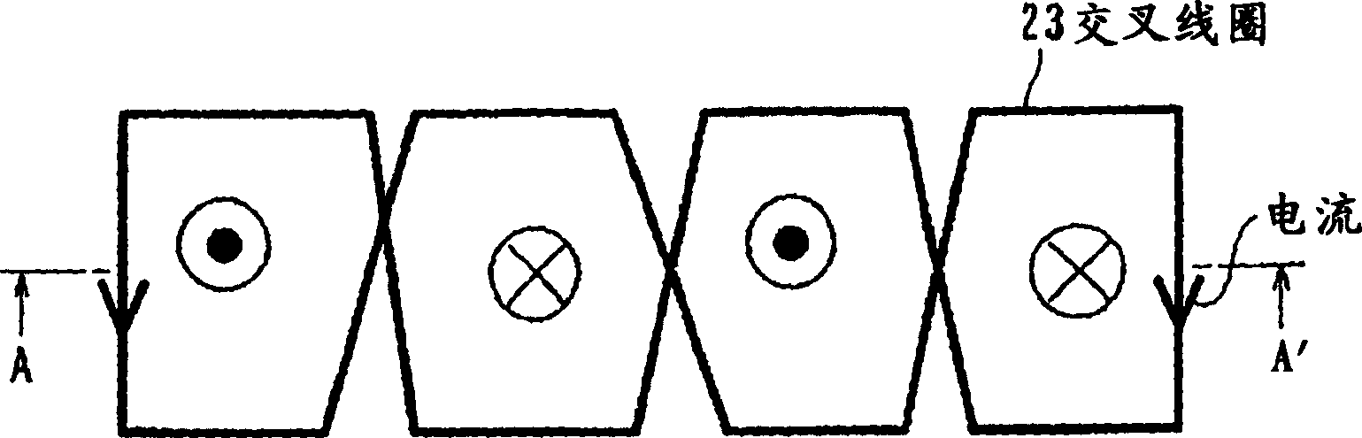
[0151] The high-frequency coil assembly 114 is placed on the top plate 104A. The high-frequency coil...


PUM


Abstract

The high-frequency coil assembly of the present invention includes a first high-frequency coil, a second high-frequency coil, and a third high-frequency coil. The first high-frequency coil receives first magnetic resonance signals from the subject. The second high-frequency coil receives at least one of the first magnetic resonance signal and the second magnetic resonance signal from the subject. The third high-frequency coil receives at least one of the first magnetic resonance signal, the second magnetic resonance signal, and the third magnetic resonance signal from the subject. In addition, the third high-frequency coil has a different shape from at least one of the first high-frequency coil and the second high-frequency coil, so that the local sensitivity of the imaging region can be improved.

Description

technical field [0001] The present invention relates to a high-frequency coil assembly for collecting magnetic resonance signals based on magnetic resonance phenomena from a subject, and a magnetic resonance imaging apparatus having the high-frequency coil assembly. Background technique [0002] Magnetic resonance imaging performed by a magnetic resonance (MRI) imaging device is a high-frequency signal of its Larmor frequency that is used to magnetically excite the nuclear spins of the subject placed in a static magnetic field. Magnetic resonance (MR) signal reconstruction imaging method. [0003] To implement this imaging method, the magnetic resonance imaging apparatus has a static magnetic field magnet that generates a static magnetic field, and a mechanism that applies gradient magnetic field pulses and high-frequency magnetic field pulses to the subject in a predetermined pulse sequence. Wherein, the gradient magnetic field pulse is sent to the subject through the grad...

Claims


Application Information

Patent Timeline
Patent Type & Authority Applications(China)
IPC IPC(8): A61B5/055G01R33/32G01R33/341G01N24/00
Inventor 冈本和也光井信二石井学
Owner TOSHIBA MEDICAL SYST CORP
Why Eureka
Try Eureka