Horizontal inclined rotary fluidized bed desulfurizing reactor
A tilt-rotating, reactor technology, applied in chemical instruments and methods, chemical/physical processes, dispersed particle separation, etc., can solve the problems of local accumulation, low desulfurization reaction efficiency, etc.
- Summary
- Abstract
- Description
- Claims
- Application Information
AI Technical Summary
Problems solved by technology
Method used
Image
Examples
specific Embodiment approach 1
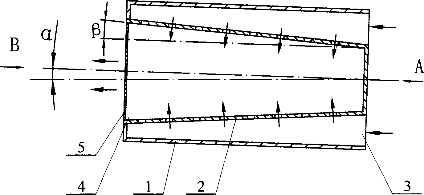
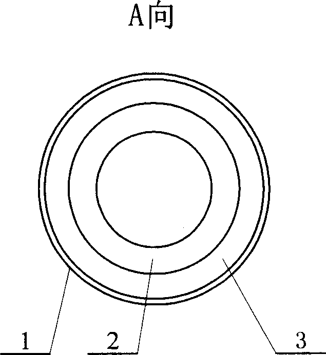
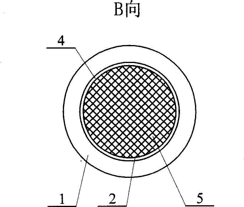
[0005] Specific implementation mode one: (see Figure 1-Figure 3 ) The horizontal inclined rotary fluidized bed desulfurization reactor described in this embodiment has an inner and outer double cylinder structure, which includes an outer cylinder 1 and an inner cylinder 2, the inner cylinder 2 is placed in the outer cylinder 1, and the inner cylinder 2 and the outer cylinder 1 The gas inlet channel is formed between them, the outer cylinder 1 is a cylindrical straight cylinder, the inner cylinder 2 is a truncated conical shape, the circumferential wall of the inner cylinder 2 is an air distribution plate structure, the cone angle β of the inner cylinder 2 is 0.5 to 12 degrees, and the inner cylinder 2 The small-diameter end is closed, and the annular channel inlet 3 is formed between the small-diameter end of the inner cylinder 2 and the outer cylinder 1, the large-diameter end of the inner cylinder 2 is the gas outlet 4, and the outer wall of the large-diameter end of the inn...
specific Embodiment approach 2
[0006] Specific implementation mode two: (see Figure 1-Figure 3 ) The difference between this embodiment and the first embodiment is that the cone angle β of the inner cylinder 2 is 2 degrees, and the angle α formed between the axis of the reactor and the horizontal plane is 3.0 degrees. Other compositions and connections are the same as in the first embodiment. The temperature is 165℃, containing 3000ppmSO 2 , the flow rate is 620000m 3 / h gas enters the small-diameter end of the inner cylinder 2 and the outer cylinder 1 to form an annular channel inlet 3 and the inner cylinder 2, and the treated gas, after desulfurization reaction, contains SO 2 The concentration is reduced to 100ppm, and the desulfurization efficiency is 96.6%.
specific Embodiment approach 3
[0007] Specific implementation mode three: (see Figure 1-Figure 3 ) The difference between this embodiment and the first embodiment is that the cone angle β of the inner cylinder 2 is 3.9 degrees, and the angle α formed between the axis of the reactor and the horizontal plane is 3.9 degrees. Other compositions and connections are the same as in the first embodiment. The temperature is 160℃, containing 2400ppmSO 2 , the flow rate is 600000m 3 / h gas enters the small-diameter end of the inner cylinder 2 and the outer cylinder 1 to form an annular channel inlet 3 and the inner cylinder 2, and the treated gas, after desulfurization reaction, contains SO 2 The concentration is reduced to 200ppm, and the desulfurization efficiency is 91.6%.
PUM
 Abstract
Description
Claims
Application Information
 - R&D
- Intellectual Property
- Life Sciences
- Materials
- Tech Scout
- Unparalleled Data Quality
- Higher Quality Content
- 60% Fewer Hallucinations
Browse by: Latest US Patents, China's latest patents, Technical Efficacy Thesaurus, Application Domain, Technology Topic, Popular Technical Reports.
© 2025 PatSnap. All rights reserved.Legal|Privacy policy|Modern Slavery Act Transparency Statement|Sitemap|About US| Contact US: help@patsnap.com


