
Reinforcement member, method of manufacturing reinforcement member, and engine block

A manufacturing method and component technology, applied in the direction of engine components, machines/engines, and rotating parts that resist centrifugal force, can solve problems such as poor adhesion, reduced thermal expansion suppression effect, and low strength, and achieve light weight and thermal expansion. Manufacturing Effects of cost reduction and low thermal expansion

Inactive Publication Date: 2006-08-30
NHK SPRING CO LTD
View PDF3 Cites 4 Cited by
  • Summary
  • Abstract
  • Description
  • Claims
  • Application Information

AI Technical Summary

Problems solved by technology

First, in the technology described in Patent Document 1, although thermal expansion is suppressed, the adhesion between the aluminum alloy material and the iron-based material that is a reinforcing member is poor, and the iron-based material is peeled off from the aluminum alloy material.
Therefore, as a composite material, there is a problem that the strength is low and the effect of suppressing thermal expansion is reduced due to the peeling.
Therefore, when it is applied to the structure of the journal, it is not ideal because it tends to generate noise or vibration.
In addition, since iron-based materials are used, the weight becomes heavy, which is not ideal for the purpose of weight reduction
[0012] Although the technology described in Patent Document 2 is a technology for improving the adhesion between the aluminum alloy material and the iron-based material that is the reinforcing member, it still requires a plating process and an annealing process, which increases the cost.
In the technology described in Patent Document 3, a metal matrix composite material must be separately produced, and a heat treatment process is required, which increases the cost

Method used


Image

  • Reinforcement member, method of manufacturing reinforcement member, and engine block
  • Reinforcement member, method of manufacturing reinforcement member, and engine block
  • Reinforcement member, method of manufacturing reinforcement member, and engine block

Examples


Embodiment Construction

[0029] 1. Composition of Embodiment

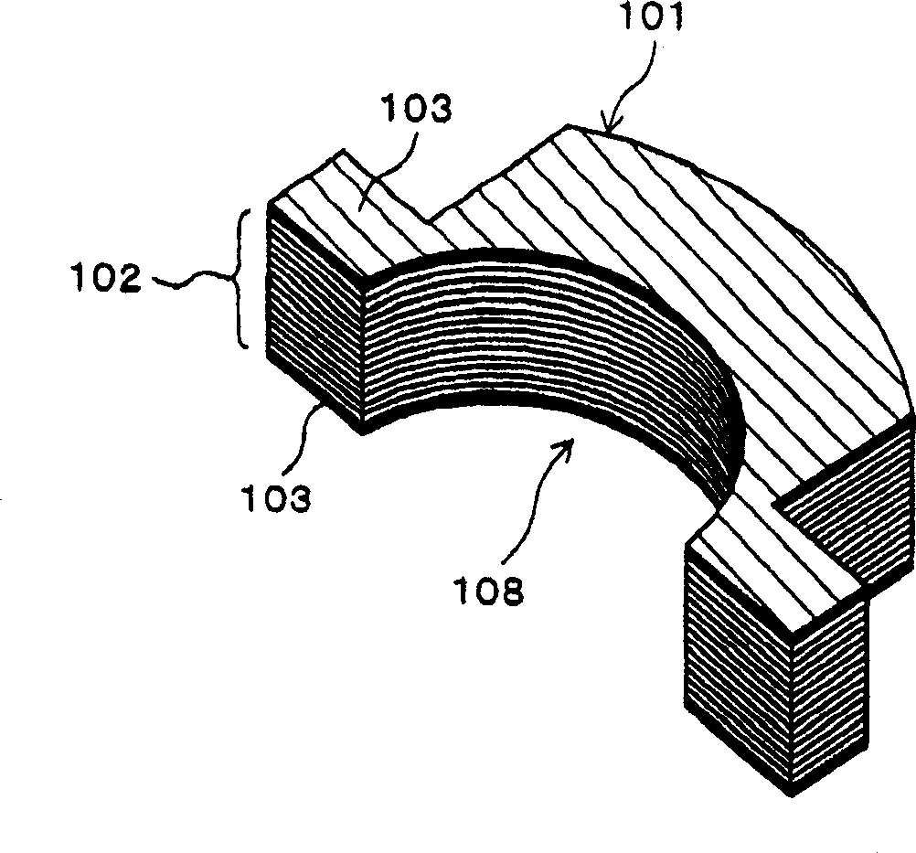
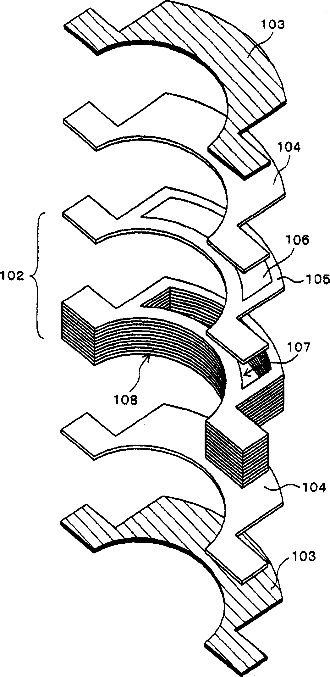
[0030] figure 1 It is a perspective view which shows the outline of the reinforcement member of this embodiment. figure 2 is the decomposition representation figure 1 An exploded perspective view of the reinforcement components shown. The reinforcing member 101 has a structure in which a laminated structure 102 formed by stacking thin iron plates, an iron plate 104 for closing an opening, and a porous body 103 are closely adhered to each other by sintering.

[0031] The laminated structure 102 is a main member constituting the reinforcing member 101 and has a hollow portion 107 formed therein. The laminated structure 107 has a structure in which multiple layers of iron plates 105 are stacked, and the iron plates 105 are punched to form an opening 106 constituting a hollow portion 107 . That is, the hollow portion 107 is formed by overlapping the opening portion 106 .

[0032] On the upper surface and the lower surface of the laminate...


PUM


Abstract

A reinforcement member, wherein a part of the reinforcement member is formed of a laminated structure (102) obtained by laminating a large number of steel plates (105) having openings (106) formed therein. A hollow portion (107) is formed in the laminated structure (102) to reduce the weight thereof. Also, porous bodies (103) formed of nonwoven fabric of metal fiber are disposed on the surfaces of the laminated structure in contact with matrixes to increase the adhesiveness thereof to the matrixes so as to prevent the separation of the reinforcement member from the matrixes. A cast product of light metal using the reinforcement member is small in thermal expansion though its weight is small and, for example, suitable for the journal part of an engine block.

Description

technical field [0001] The present invention relates to a reinforcing member for reinforcing light metals used in automobile parts, aircraft parts, and the like. Background technique [0002] Aluminum alloys are used in many fields, such as automobile parts and aircraft parts, to achieve weight reduction. Aluminum alloys have the advantage of being lightweight, but have the problem of large thermal expansion when exposed to high temperatures. [0003] For example, in order to achieve weight reduction, it is known to form an engine body of an automobile engine from an aluminum alloy. In the engine body, there is a journal portion (journal bearing portion) which is a bearing for supporting the crankshaft. [0004] In the case where the engine body is formed of an aluminum alloy for weight reduction as described above, it is desirable that the journal also be formed of an aluminum alloy. This is because if there is a difference in thermal expansion rate among the parts const...

Claims


Application Information

Patent Timeline
Patent Type & Authority Applications(China)
IPC IPC(8): B22D19/14B22D19/08B22D19/02B22D19/00F02F7/00F16C33/14C22C47/12F16C9/02F16F15/02
CPCF16C9/02B22D19/14F16C33/14F16C2220/20F16C2223/32F16C2220/82F16C2226/34Y10T428/12493Y10T428/249953Y10T428/249927Y10T428/249921Y10T428/249955Y10T428/249971C22C21/00
Inventor 白石透胜矢晃弘
Owner NHK SPRING CO LTD
Features
  • Generate Ideas
  • Intellectual Property
  • Life Sciences
  • Materials
  • Tech Scout
  • Unparalleled Data Quality
  • Higher Quality Content
  • 60% Fewer Hallucinations
Learn More