Broadband single-polarization single-mode dual-core photonic crystal fiber

A photonic crystal fiber, single-polarization technology, used in cladding fibers, optical waveguides, light guides, etc.

Inactive Publication Date: 2006-09-27
NANKAI UNIV
View PDF1 Cites 23 Cited by
  • Summary
  • Abstract
  • Description
  • Claims
  • Application Information

AI Technical Summary

Problems solved by technology

However, to the best of our knowledge, there have not been any reports on

Method used


Image

  • Broadband single-polarization single-mode dual-core photonic crystal fiber
  • Broadband single-polarization single-mode dual-core photonic crystal fiber
  • Broadband single-polarization single-mode dual-core photonic crystal fiber

Examples


Embodiment Construction

[0021] The specific embodiment of the present invention will be further described below in conjunction with accompanying drawing:

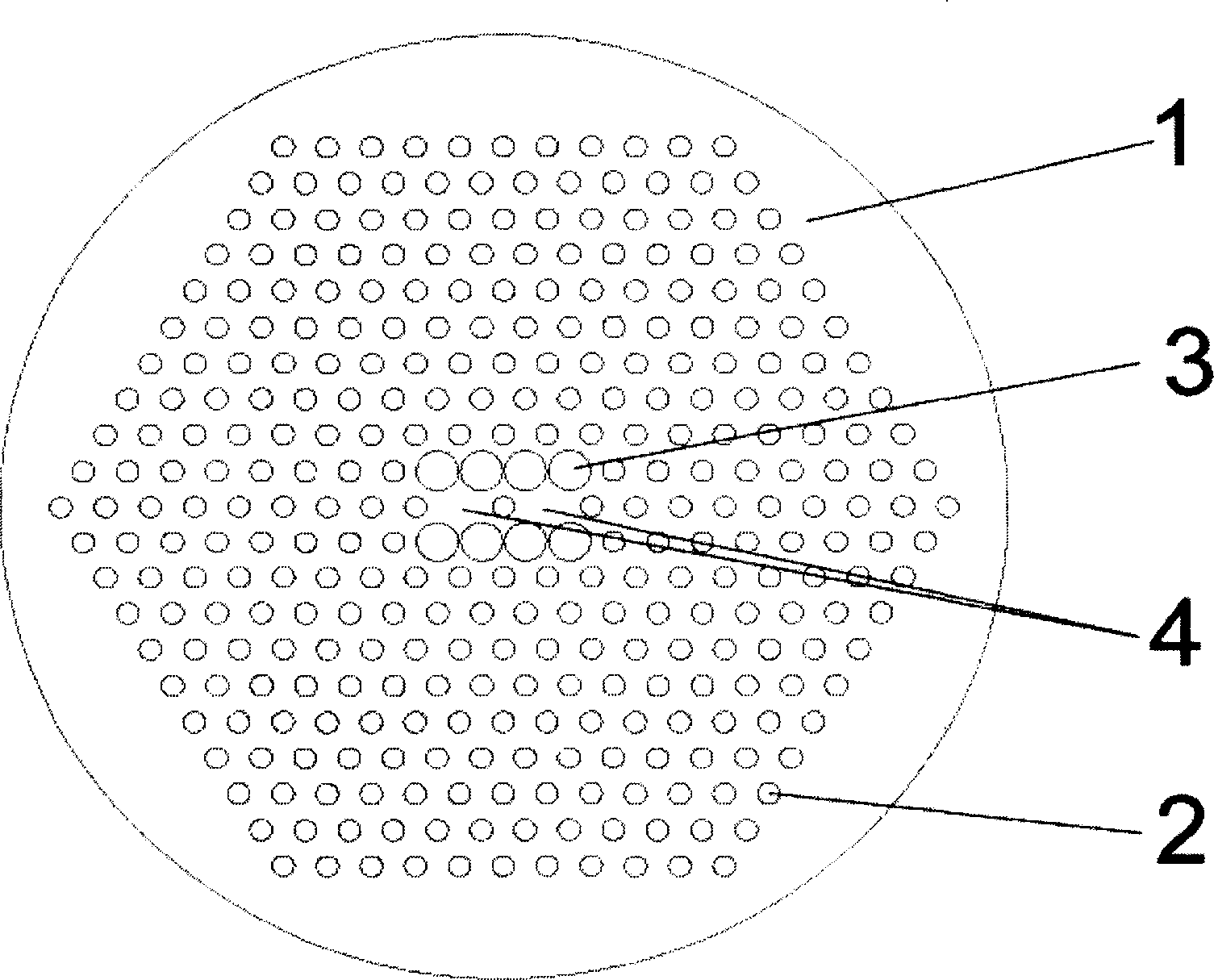
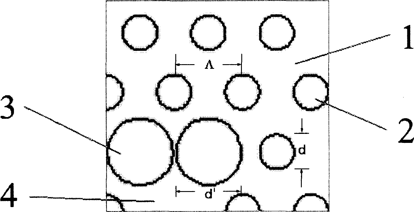
[0022] The cladding of this broadband single-polarization single-mode dual-core photonic crystal fiber is formed by arranging air holes 2 and 3 in a regular network structure on the substrate, and two defect cores 4 are formed by the absence of cladding air holes, which are characterized in that : The sizes of the air holes near the two core regions are different in the two orthogonal polarization directions of the fiber cross-section, and the above-mentioned cross-sectional structure is constant along the length direction of the fiber.

[0023]The air holes in the fiber cladding are arranged in a triangular grid, and the two defect cores are located at the nodes of the triangular grid.

[0024] The air hole in the cladding layer and the defect core on the cross section of the fiber can be circular, and the diameter of the hole in the X direction ...


PUM


Abstract

This invention relates to a broadband single-polarization single-mode dual-core photonic crystal fiber. To the fiber communication and optical signal process, This scheme comprises: forming the envelop by arraying air port as regular network structure on substrate, and forming two defect fiber cores by the air port defect; arranging different air ports near the port zones on orthogonal polarization directions of fiber cross section, and keeping the cross section structure along fiber lateral direction. This invention can regulate the coupling wavelength by adjusting the larger air port diameter d' or the smaller d.

Description

technical field [0001] The invention relates to a single-mode photonic crystal fiber, in particular to a double-core photonic crystal fiber with broadband single-polarization transmission characteristics. It is used in technical fields such as optical fiber communication and optical signal processing. Background technique [0002] Photonic Crystal Fiber, also known as Microstructure Optical Fiber or Hole Fiber, was first manufactured by J.C.Knight et al. in R.J.Russell group in 1996 (Optics Letters, 21 , 1547-1549, 1996). Because of its flexible design and many properties that cannot be realized by ordinary optical fibers (such as single-mode conduction with no cut-off wavelength, programmable dispersion characteristics and mode field size, and high numerical aperture, etc.), it has attracted extensive attention. Photonic crystal fibers are classified into two types. The first type is the refractive index conduction photonic crystal fiber, which guides light through total...

Claims


Application Information

Patent Timeline
IPC IPC(8): G02B6/02
Inventor 开桂云王志岳洋刘艳格袁树忠董孝义
Owner NANKAI UNIV
Why Eureka
Try Eureka