Liquid crystal display device

A technology of liquid crystal display device and liquid crystal display panel, which is applied to static indicators, light guides, optics, etc., can solve the problems of difficulty in cooling the light source, great labor for exchange or cleaning, insufficient cooling function of LEDs, etc., and achieves excellent cooling function. , the effect of high brightness color reproducibility

Inactive Publication Date: 2006-09-27
SHARP KK
View PDF1 Cites 20 Cited by
  • Summary
  • Abstract
  • Description
  • Claims
  • Application Information

AI Technical Summary

Problems solved by technology

However, even for LEDs with a self-cooling function, it is still in a state that only using such an LED cooling function is not sufficient, and other cooling methods are still indispensable.
In particular, it is difficult to cool the light source of the backlight unit for display devices and notebook personal computers that require miniaturization and narrow margins.
For example, if forced cooling by fans is used, the size of the backlight unit will increase
In addition, due to the failure of the fan or the clogging of the filter, etc., it is necessary to spend a lot of labor on replacement or cleaning.
On the other hand, in the case of liquid cooling, a refrigerant is required, and there is a possibility of liquid leakage

Method used


Image

  • Liquid crystal display device
  • Liquid crystal display device
  • Liquid crystal display device

Examples


Embodiment Construction

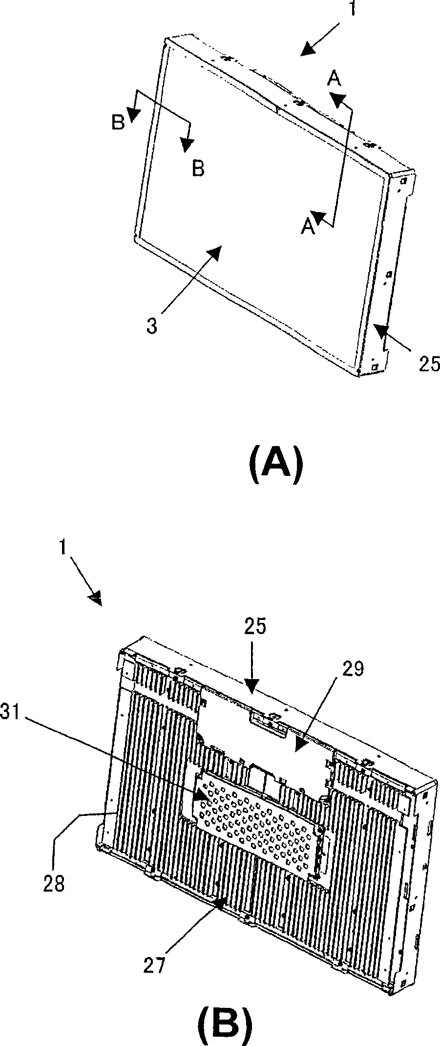
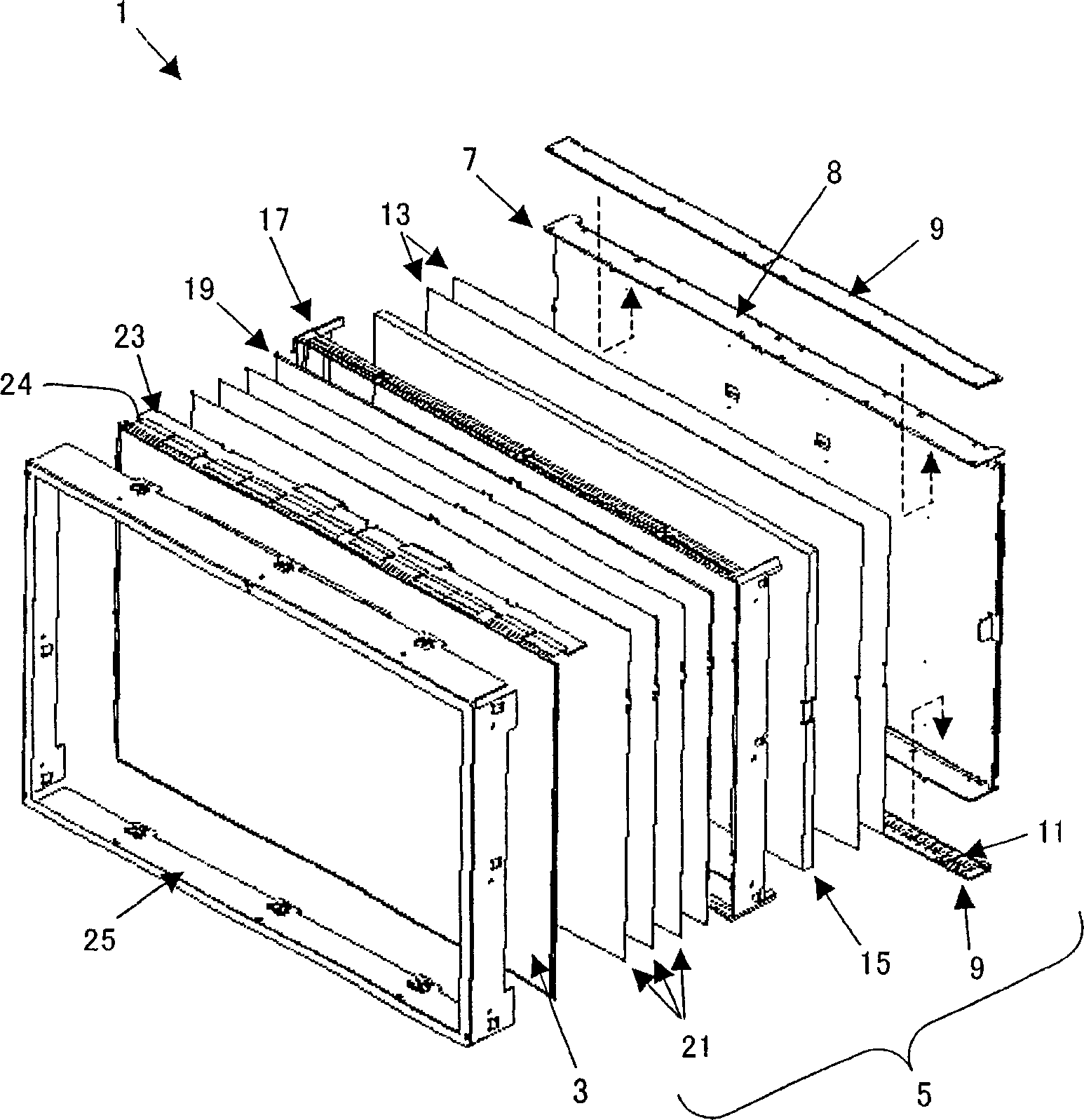
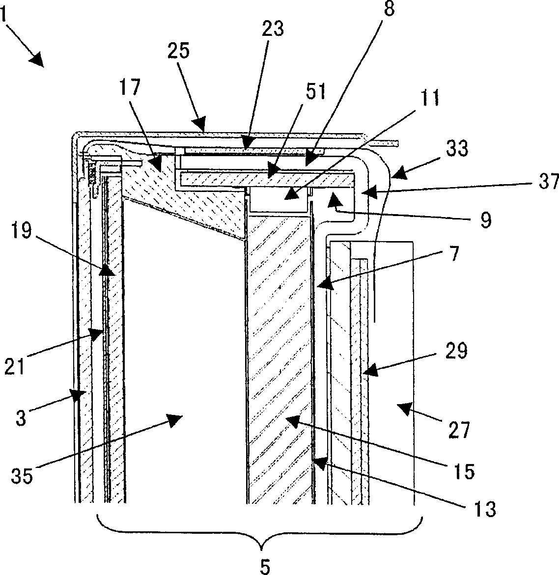
[0026] use figure 1 A~ Figure 14 A liquid crystal display device according to one embodiment of the present invention will be described. First, use figure 1 A~ figure 2 A schematic configuration of the liquid crystal display device of this embodiment will be described. figure 1 A is a perspective view of the liquid crystal display device 1 viewed from the display screen side, figure 1 B is a perspective view of the liquid crystal display device 1 viewed from the rear side of the display screen. figure 2 It is an exploded perspective view of the liquid crystal display device 1 . Such as figure 1 A~ figure 2 As shown, a liquid crystal display device (liquid crystal display unit) 1 includes a liquid crystal display panel 3 sealing liquid crystal between two opposing substrates, and a backlight unit 5 arranged behind the liquid crystal display panel 3 . The light source of the backlight unit 5 is a high-brightness high-power LED 11 with a self-cooling function. Furthe...


PUM


Abstract

The invention relates to a liquid crystal display used as a display unit of an electronic apparatus and provides a small liquid crystal display having a thin picture frame, the display having an excellent cooling function, high luminance, and high color reproducibility. The liquid crystal display includes a rear frame having an upstanding portion formed by bending an end of a longer side thereof and a heat sink which is in thermal contact with the rear frame. Thus, heat generated at LEDs can be efficiently radiated. The liquid crystal display also includes a liquid crystal display panel driving circuit which is divided into a data substrate and a control substrate. The liquid crystal display can be provided in a compact structure having a thin picture frame by disposing the data substrate on a side surface of the liquid crystal display and disposing the control substrate on the side of the heat sink.

Description

technical field [0001] The present invention relates to a liquid crystal display device used in a display portion of electronic equipment. Background technique [0002] Most of the backlight units currently on the market use cold-cathode tubes as light sources, but backlight units using LEDs have also been developed. Liquid crystal display devices using backlight units using LEDs as light sources have been installed in small electronic devices such as PDAs and mobile phones. In addition, in recent years, high-brightness high-power LEDs with a self-cooling function have been developed. A large-screen liquid crystal display device used in a display device equipped with a backlight unit using a high-power LED as a light source has been announced at an exhibition or the like. [0003] Patent Document 1: Japanese Patent Laid-Open No. 2002-040413 [0004] The problem to be solved by the invention [0005] There is a limit in color reproducibility between a backlight unit using...

Claims


Application Information

Patent Timeline
Patent Type & Authority Applications(China)
IPC IPC(8): G02F1/133G02F1/1335G02F1/13357G09G3/20
CPCG02B6/0088G02F2001/133628G02F2001/133314G02F1/133308G02B6/0085G02F2001/133317H05K7/20972G02F1/133317G02F1/133314G02F1/133628G02F1/1333G02F1/1335
Inventor 石和优永乐敬之
Owner SHARP KK
Why Eureka
Try Eureka