Permanent-magnet synchronous motor rotor position sensing method and position sensing device

A technology of permanent magnet synchronous motor and rotor position, which is applied in the field of resolver to achieve the effects of high reliability, convenient installation and disassembly, and simple structure

Active Publication Date: 2006-09-27
BYD CO LTD
View PDF0 Cites 60 Cited by
  • Summary
  • Abstract
  • Description
  • Claims
  • Application Information

AI Technical Summary

Problems solved by technology

[0003] The technical problem to be solved by the present invention is to propose a permanent magnet synchronous motor rotor position sensing method that is compatible with the complex electromagnetic environment of electric vehicles and is suitable for use...

Method used


Image

  • Permanent-magnet synchronous motor rotor position sensing method and position sensing device
  • Permanent-magnet synchronous motor rotor position sensing method and position sensing device
  • Permanent-magnet synchronous motor rotor position sensing method and position sensing device

Examples


Embodiment Construction

[0033] A permanent magnet synchronous motor rotor position sensing device used in BYD EVF3 electric vehicle

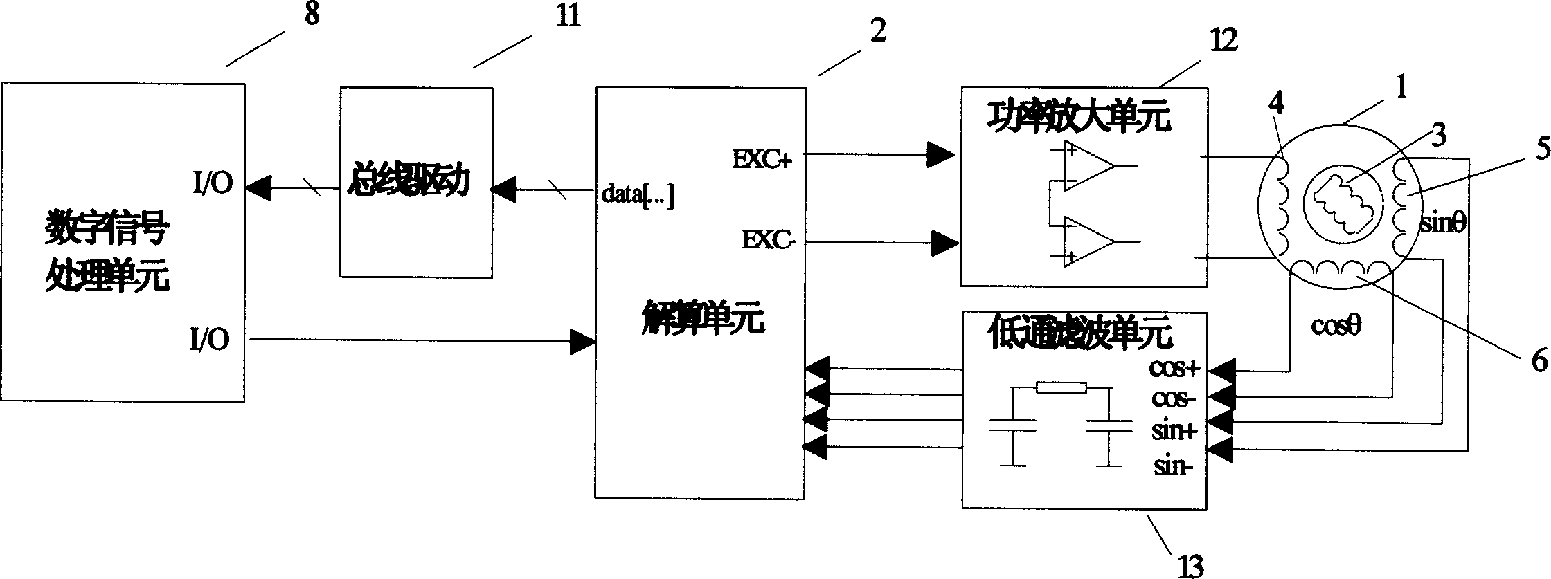
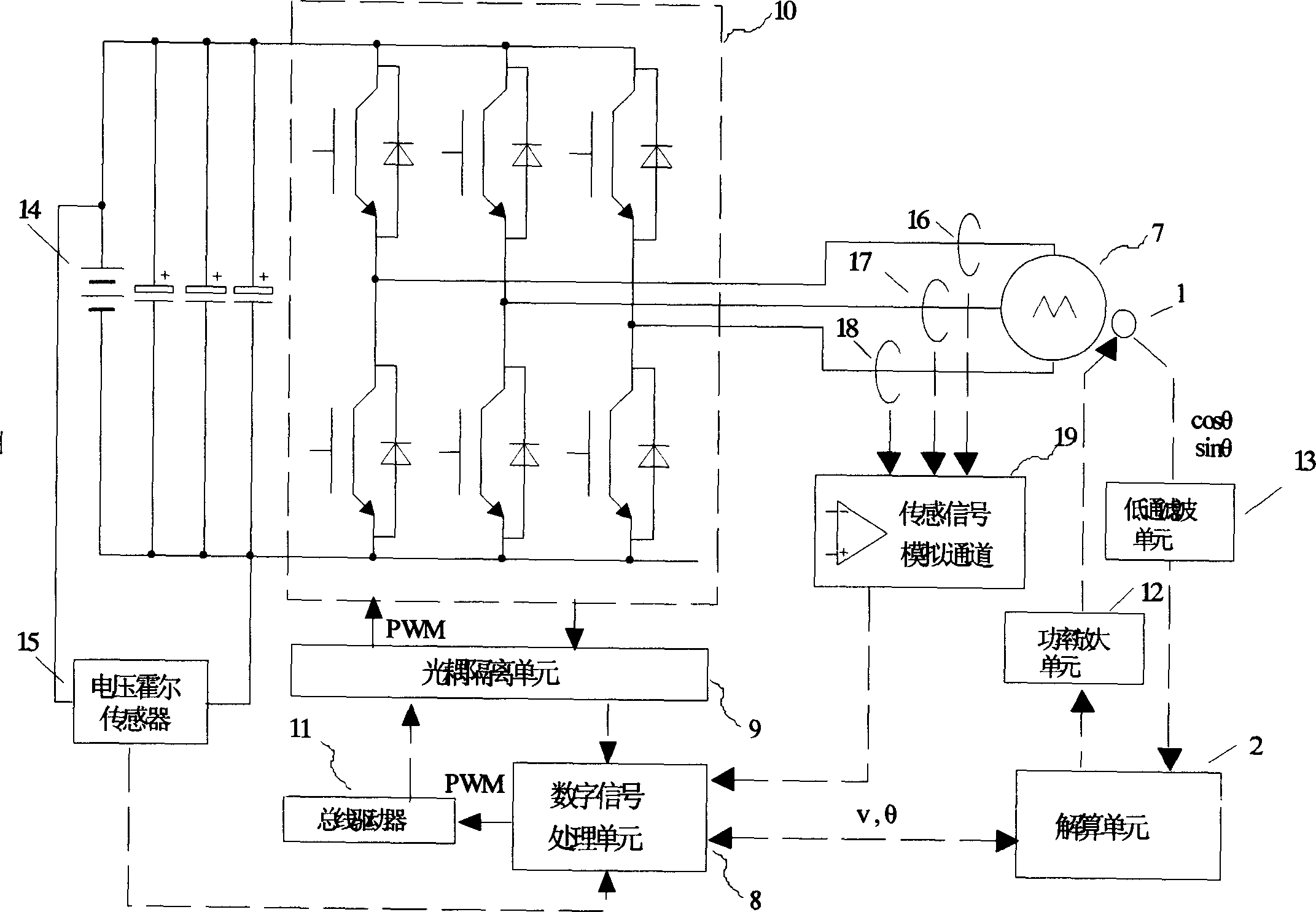
[0034] Such as figure 1 , 2 As shown, this permanent magnet synchronous motor rotor position sensing device includes a resolver 1 and a digital conversion solution unit 2 (RDC) as sensors in the current loop, speed loop and position loop control of the permanent magnet AC servo system. 1 consists of two parts, the rotor and the stator. There is a set of independent windings 3 on the rotor, and three sets of windings on the stator. One set is the input winding 4 that accepts the sine wave excitation signal from the solving unit 2, and the other set is sent to the solving unit 2. The amplitude of the calculation unit 2 is the output winding 5 of the sine wave output signal modulated by the instantaneous angular displacement signal of the motor rotor, and the other group is the output of the cosine wave output signal whose amplitude is modulated by the instantaneous angu...


PUM


Abstract

This invention discloses a permanent synchronous generator rotor location sensing method and location sensing device, which uses rotary transformer and solving cell as sensor, and it has digit signal dealing cell, where the solving cells samples detection generator location angle in real time and fixing time interval, and it judges the change of the generator location angle after each sampling to determine whether to complement and correction. If the solving cell checks out that the extent of the rotary transformer's sensing signal of the output exceeds the allowing range, then it sends the demand to control the permanent synchronous generator to stop running to the digit signal dealing cell. This invention also discloses a permanent synchronous rotor location sensing device, which is compatible with bad magnetic environment of motor car or mixed motor car, and it can keep the generator running stably under the environment that the rotary transformer or solving cell has big error or invalidate. So this invention can be applied extensively in electric servo system of middle or small power including electric automobile and mixing motor car' driving part.

Description

technical field [0001] The invention relates to a rotary transformer suitable for special purposes or functions, in particular to a rotor position sensing method and a position sensing device of a permanent magnet synchronous motor using the rotary transformer. Background technique [0002] A brushless synchronous motor (PMSM) driven by a sine wave, that is, a permanent magnet AC servo motor, has higher energy density and efficiency compared with an induction motor and an ordinary synchronous motor, and has small size, low inertia, fast response and simple control And other advantages, gradually become the mainstream of AC servo system executive motor, especially in the field of small and medium power servo with high precision and high performance requirements. It is very suitable for the drive system of electric vehicles and hybrid vehicles, and it is also a research and development hotspot for electric vehicles and hybrid vehicles. In the PMSM control system, not only the...

Claims


Application Information

Patent Timeline
IPC IPC(8): H02P6/16H02P6/17
Inventor 廖勇周旭光马先红杨广明齐阿喜王辉张金涛
Owner BYD CO LTD
Why Eureka
Try Eureka