Heat radiator with heat exchange function

A technology of heat dissipation device and cold and heat exchange, which is applied in cooling/ventilation/heating transformation, instruments, electrical digital data processing, etc. the effect of exchange

Inactive Publication Date: 2006-10-04
CHANNEL WELL TECH
View PDF0 Cites 0 Cited by
  • Summary
  • Abstract
  • Description
  • Claims
  • Application Information

AI Technical Summary

Problems solved by technology

The effect achieved by the above-mentioned heat dissipation method is related to the ambient temperature, that is, the temperature at which it can achieve equilibrium is at most equal to the room temperature, and the heat dissipation method through gas convection is often inefficient.
Therefore, a heat dissipation device is needed to solve the problem of limited heat dissipation efficiency encountered in conventional heat dissipation fan-based heat dissipation systems.

Method used


Image

  • Heat radiator with heat exchange function
  • Heat radiator with heat exchange function
  • Heat radiator with heat exchange function

Examples


Embodiment Construction

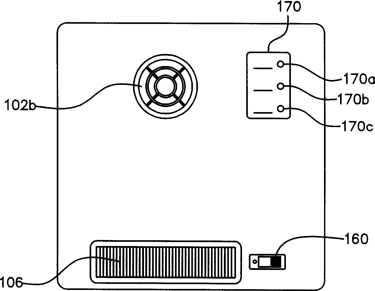
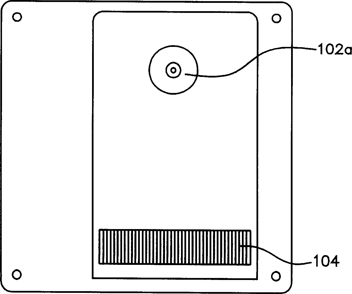
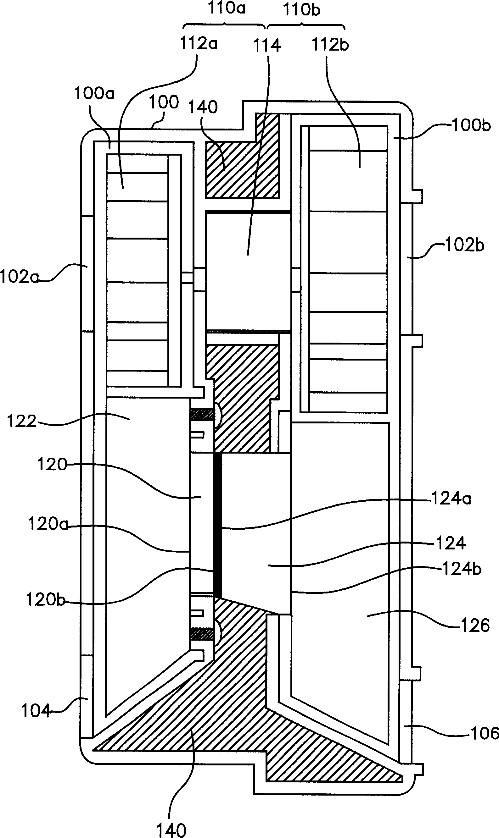
[0034] see Figures 1A to 1C , Figure 1A , 1B A front view and a rear view of a preferred embodiment of a cooling device with cooling and heat exchanging functions according to the present invention are shown respectively. Figure 1C for Figure 1A side profile view. The heat dissipation device with heat exchange function mainly includes a housing 100 , a first flow guiding device 110 a , a cooling chip 120 and a second flow guiding device 110 b.

[0035] The casing 100 includes a first space 100 a with a first air inlet 102 a and a cold air outlet 104 , and a second space 100 b with a second air inlet 102 b and a hot air outlet 106 . The first flow guiding device 110a is located next to the first air inlet 102a, and is used to guide a heat source fluid to enter the housing 100 from the first air inlet 102a, the heat source fluid flows out of the housing from the cold air outlet after being cooled, and the external environment fluid passes through After heat exchange, the ...


PUM


Abstract

The heat sink with cold and hot exchange function comprises a shell with a first and second room to couple with the cold and hot sides of following chip, a first / second guide device, and a refrigeration chip.

Description

technical field [0001] The present invention relates to a heat dissipation device, and in particular to a heat dissipation device with cold and heat exchange functions suitable for electronic equipment. Background technique [0002] With the high development of information technology, such as the improvement of integrated circuit manufacturing process, and the increasing requirements for the functional specifications of integrated circuits, the design of integrated circuits today is very delicate and complex. Due to the huge power consumption caused by the complex circuit design, the power consumption will cause the temperature of the chip to rise. [0003] Related components based on integrated circuits are very important in the application of computers. In consideration of cost and space saving, it is difficult to reserve enough space for natural convection in the design of current computer casings. Therefore, components on the computer, such as the central processing unit...

Claims


Application Information

Patent Timeline
IPC IPC(8): G06F1/20H05K7/20
Inventor 潘君威
Owner CHANNEL WELL TECH
Why Eureka
Try Eureka