Self-circulation cooling loop of heavy current fixture wire

A cooling circuit, high-current technology, applied in the direction of transformer/inductor cooling, energy-saving heating/cooling, lighting and heating equipment, etc., to achieve the effect of simple lead structure, good fire protection, and safe operation

Inactive Publication Date: 2006-10-04
INST OF ELECTRICAL ENG CHINESE ACAD OF SCI
View PDF0 Cites 12 Cited by
  • Summary
  • Abstract
  • Description
  • Claims
  • Application Information

AI Technical Summary

Problems solved by technology

[0005] For overcoming the shortcoming of prior art, the present invention aims at current density at 2.5A / mm 2 The above high-current leads propose a self-circulating evaporative cooling circuit, using a gas-liquid separation device, using the buoyancy of the gas and the power formed by the fluid density difference to overcome the flow resistance along the process, and realize the cooling without external power intervention. self circulation

Method used


Image

  • Self-circulation cooling loop of heavy current fixture wire
  • Self-circulation cooling loop of heavy current fixture wire
  • Self-circulation cooling loop of heavy current fixture wire

Examples


Embodiment Construction

[0023] The present invention will be further described below in conjunction with the accompanying drawings and specific embodiments.

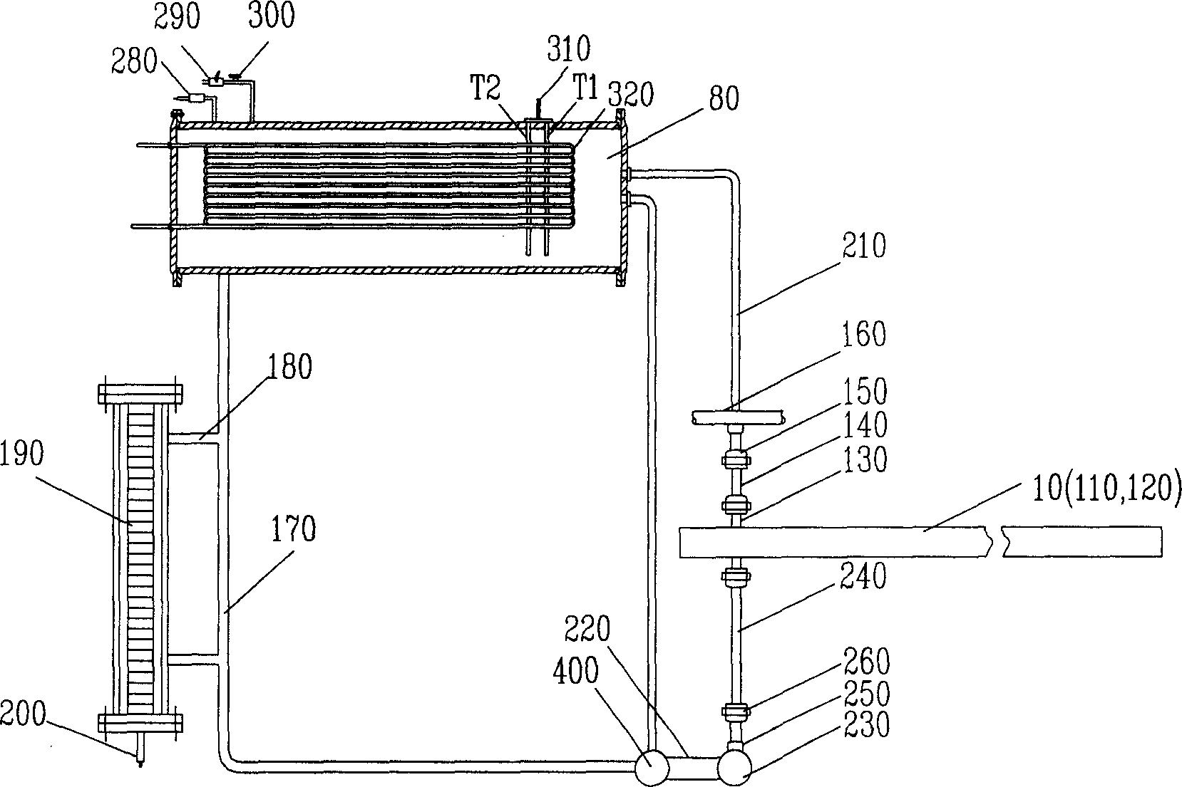
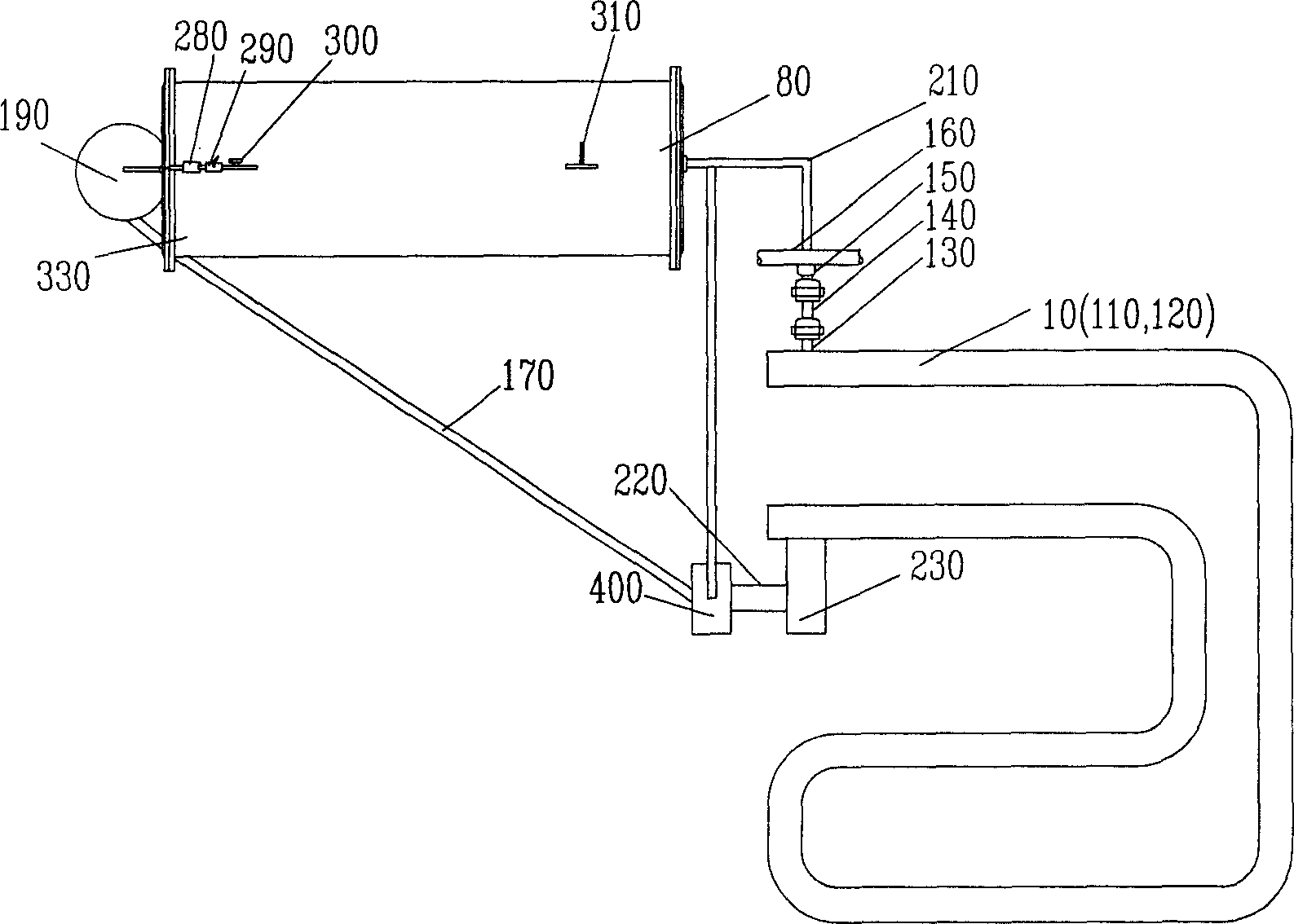
[0024] As shown in Figure 1, it is an embodiment of a hollow thick-walled tubular wire. The lead wire 10 of the large current equipment is composed of a thick-walled hollow pipeline 120 with a circular cross-section, which is placed horizontally. The outlet end is connected with the upper insulating lead pipe 140 through the upper electro-hydraulic separation joint 130 . The upper insulating lead pipe 140 is connected with the gas collecting pipe 160 through the sealing joint 150 . The air collecting pipe 160 enters the cooling space of the condenser 80 through the intake pipe 210 . The condenser 80 is connected to the liquid return pipe 170 . The magnetic float level gauge 190 is connected with the liquid return pipe 170 through the connection pipe 180 . A pressure sensor 200 is installed at the lower end of the liquid level gauge 190 , an...


PUM

PropertyMeasurementUnit
boiling pointaaaaaaaaaa

Abstract

The invention relates to a large current equipment pin equipment cooler circuit. It is characterized in that it comprises a large current device pin (10) and an evaporative cooling circulation system; the large current device pin (10) is formed by a solid conductor and circular or polygonal hollow conductor or hollow pipe conductor; it injects the evaporative cooling media in the hollow conductor. The current can lead the loss and the winding heats whose heat transmits to the cooling media of the hollow conductor, when the temperature lifts to the corresponding saturation temperature; the winding inner hollow conductor evaporative cooling media evaporates to form boiling heat transfer and then uses cooler to be liquefied, and then cycles.

Description

technical field [0001] The invention relates to a self-circulation cooling circuit for lead wires of high-current equipment of electrical equipment, in particular to a self-circulation cooling circuit for lead wires of hydroelectric generators and high-current transformers. Background technique [0002] With the development of large-scale electrical equipment, the increase in temperature caused by the increase of current and heat has become a bottleneck restricting its development. [0003] According to different cooling methods, the cooling methods of lead wires are usually divided into two types: air cooling and water internal cooling. The air-cooling method reduces the current density by increasing the number of parallel branches and increasing the cross-sectional area of ​​the over-current, and adopts measures such as setting a windshield to appropriately reduce the over-current area at the upper end of the stator to increase the wind speed at the lead wire and achieve t...

Claims


Application Information

Patent Timeline
Patent Type & Authority Applications(China)
IPC IPC(8): H02K9/19H01F27/18F25B15/00
CPCY02B30/62Y02A30/27
Inventor 袁佳毅顾国彪田新东阮琳余顺周宋福川李振国国建鸿
Owner INST OF ELECTRICAL ENG CHINESE ACAD OF SCI
Why Eureka
Try Eureka