
Apparatus for conducting stack gas desulfurization with limestone grout tank arranged in lower position and method thereof

A technology for limestone slurry and desulfurization process, which is applied in separation methods, chemical instruments and methods, dispersed particle separation, etc., to achieve the effects of reducing height, occupying a small site area, and low cost.

Inactive Publication Date: 2006-10-11
GUODIAN TECH & ENVIRONMENT GRP
View PDF0 Cites 6 Cited by
  • Summary
  • Abstract
  • Description
  • Claims
  • Application Information

AI Technical Summary

Problems solved by technology

[0005] The present invention proposes an improved flue gas desulfurization process low-position limestone slurry preparation device and its method, which solves the problems of reducing civil engineering volume and project cost, reducing material costs, reducing equipment footprint, and improving work efficiency

Method used


Image

  • Apparatus for conducting stack gas desulfurization with limestone grout tank arranged in lower position and method thereof
  • Apparatus for conducting stack gas desulfurization with limestone grout tank arranged in lower position and method thereof

Examples


Embodiment 1

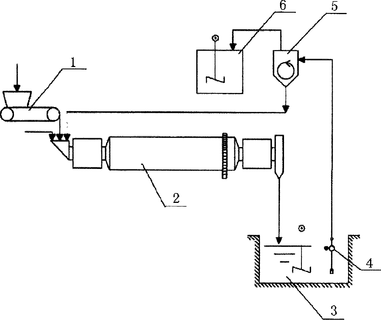
[0023] Embodiment one sees figure 1 : The wet ball mill limestone pulping system of the present invention can be divided into I-level recirculation system and II-level recirculation system to meet the needs of different particle size slurries. Limestone from mines is usually crushed into limestone blocks larger than 20 mm. The limestone particle size required by the limestone-gypsum wet flue gas desulfurization plant must meet the requirements of a fineness of less than 63 μm and a sieve rate of 90%. At the same time, the limestone powder must be prepared into a uniform slurry before it can be added to the flue gas desulfurization plant. . When the limestone particle size only needs to be finer than 63μm and the sieve rate is 90%, use figure 1 The shown I level recycling preparation process and equipment.

[0024] In the limestone slurry preparation system of the present invention, the limestone blocks are quantitatively transported into the wet ball mill 2 through the weig...

Embodiment 2

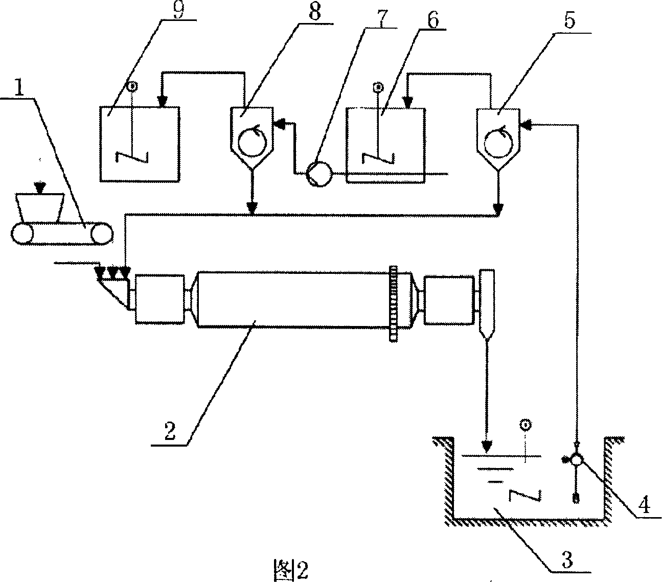
[0025] Example 2 Refer to Fig. 2: When the particle size of limestone requires a fineness of less than 31 μm and a sieving rate of 90%, the II-level recycling preparation process and device shown in Fig. 2 are generally used. The II-level recirculation system is based on the products of the I-level recirculation system, and then performs a hydrocyclone separation. After the II-level circulation separation, the slurry with a limestone particle size of less than 31 μm and a sieving rate of 90% can be obtained.

[0026] First, dig a limestone slurry tank underground to replace the previous limestone slurry tank. Second, the limestone slurry circulation pump adopts the type of submerged pump, and the pump body and impeller of the submerged pump vertically extend into the limestone slurry tank. This is because, to arrange conventional water pumps below zero meters, pump pits and corresponding accidental drainage systems need to be excavated to prevent the pumps from being submerged ...


PUM

PropertyMeasurementUnit
particle diameteraaaaaaaaaa

Abstract

The invention relates to a preparing apparatus of limestone slurry in a low place in flue gas desulfurization process and the method, a scale feeder and a wet ball mill setted on the groud, a limestone slurry pond setted under ground, the exit end of recycle liquid pump connected with a hydroclone located above the mill, the bottom outlet of the hydroclone connected with inlet of the mill by conduits, the overflow end connected with a limestone slurry storage bin. The bottoms of the storage bin Connected with delivery pipes, and connected with two-level the hydroclone by two-level circulating pump, bottom outlet of two-level hydroclone connected with inlet of the mill with conduits, overflow end of two-level hydroclone connected with two-level limestone slurry storage bin. The invention reduces cost of capital investment and equipment material, and is suitable to flue gas desulfurization project of heat power plant.

Description

(1) Technical field [0001] The invention relates to a limestone slurry preparation device and a method thereof in a limestone / lime-gypsum wet flue gas desulfurization process in a thermal power plant. (two), background technology [0002] Power plants and industrial boilers typically run on fossil fuels such as coal and oil. Because these fossil fuels generally contain sulfur components, harmful substances such as sulfur dioxide will be produced during the combustion process. Limestone-gypsum wet flue gas desulfurization devices are widely used in large power plant boilers to remove sulfur dioxide in boiler flue gas. Limestone-gypsum wet flue gas desulfurization plant needs limestone slurry as absorbent to absorb sulfur dioxide in flue gas. Limestone slurry is prepared by mixing limestone powder with a certain particle size and water, so the preparation of limestone powder is the most important process of slurry preparation. Generally, there are two systems for preparing ...

Claims


Application Information

Patent Timeline
Patent Type & Authority Applications(China)
IPC IPC(8): C04B2/08B01D53/50B01D53/78B01D53/80
Inventor 刘汉强杨东陈玉乐
Owner GUODIAN TECH & ENVIRONMENT GRP
Learn More