Method for removing mercury from mercury pollution materials
A mercury pollution and removal technology, applied to the removal of solid waste, etc., to achieve the effect of reducing mercury content
- Summary
- Abstract
- Description
- Claims
- Application Information
AI Technical Summary
Problems solved by technology
Method used
Image
Examples
example 1
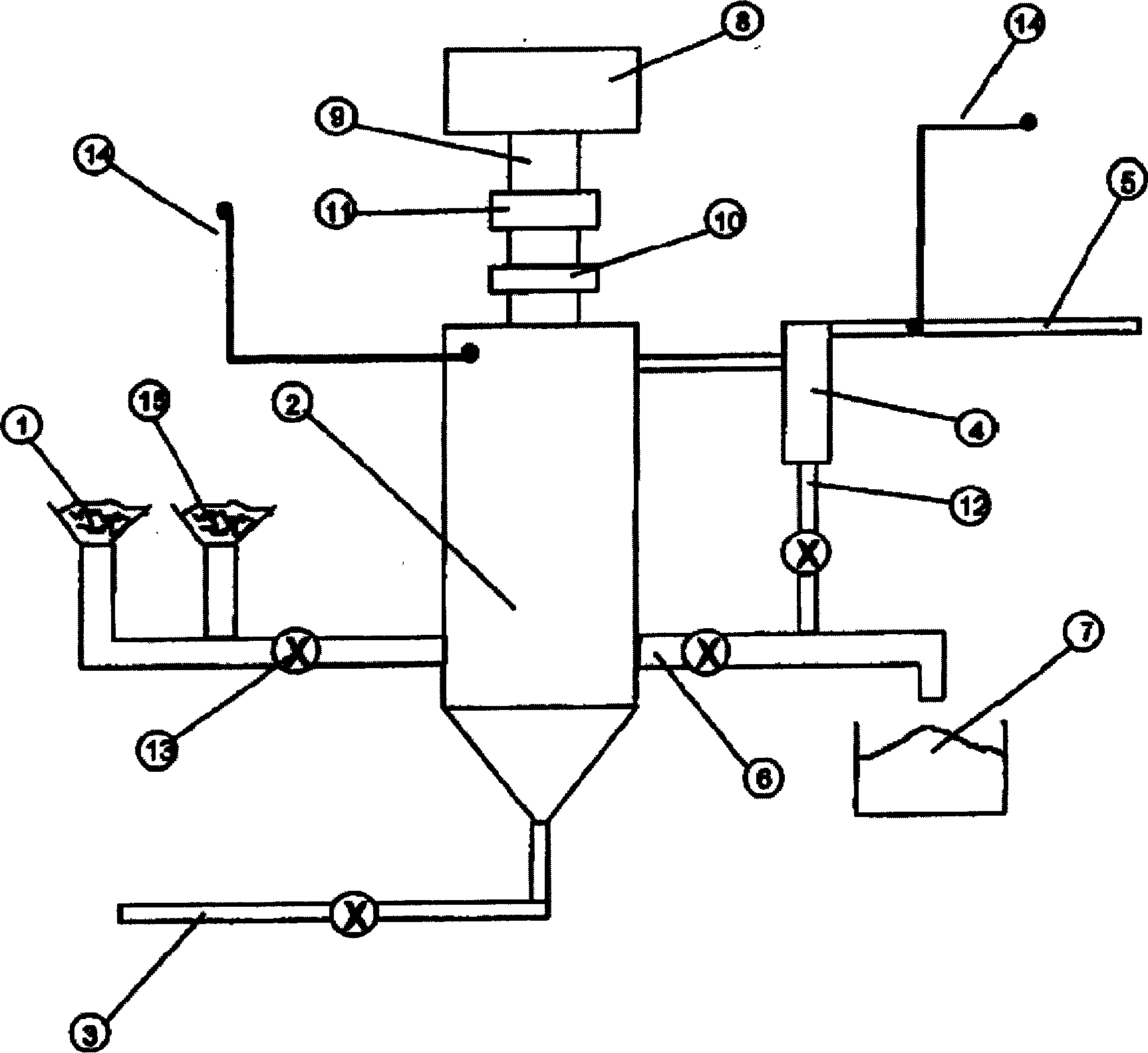
[0045] Assembled as figure 1 Schematic representation of equipment to process a quantity of coal combustion fly ash known to contain mercury. A microwave frequency of 915MHz is used. The fluidizing gas is ambient air.
[0046] The feed fly ash is processed at a temperature of about 820°C. The material passed through the reactor vessel at a rate of approximately 6 pounds per minute (lbs) throughout the approximately 400 minute duration of the test.
[0047] The mercury content in the feed was measured to be 79 parts per billion (ppb). The unburned carbon content, characterized by LOI (loss on ignition), was measured to be 8.5%.
[0048] Treated ash samples were periodically taken from the experiment and measured for mercury content. The results obtained are shown in Table 1 below. The LOI of the treated material was 1.5%.
[0049] time
[0050] As can be seen from the table, once the process has reached steady state operation with respect to mercury precipitat...
example 2
[0052] Assembled as figure 1 Schematic representation of equipment to process a quantity of coal combustion fly ash known to contain mercury. A microwave frequency of 915MHz is used. The fluidizing gas is ambient air.
[0053] The feed fly ash is processed at a temperature of about 820°C. The material passed through the reactor vessel at a rate of approximately 6 pounds per minute (lbs) throughout the approximately 500 minute duration of the test.
[0054] The mercury content in the feed was measured to be 33 parts per billion (ppb). The unburned carbon content, characterized by LOI (loss on ignition), was measured to be 17.5%.
[0055] Treated ash samples were periodically taken from the experiment and measured for mercury content. The results obtained are shown in Table 2 below. The LOI of the treated material was 0.4%.
[0056] time (min
example 3
[0058] Assembled as figure 1 Schematic representation of equipment to process a quantity of coal combustion fly ash known to contain mercury. A microwave frequency of 915MHz is used. The fluidizing gas is ambient air.
[0059] The feed fly ash is processed at a temperature of about 820°C. The material passed through the reactor vessel at a rate of approximately 6 pounds per minute (lbs) throughout the approximately 400 minute duration of the test.
[0060] The mercury content in the feed was measured to be 142 parts per billion (ppb). The unburned carbon content, characterized by LOI (loss on ignition), was measured to be 4.5%.
[0061] Treated ash samples were periodically taken from the experiment and measured for mercury content. The results obtained are shown in Table 3 below. The final LOI was 0.3%.
[0062] time
(minute)
product mercury
(ppb)
cyclone mercury
(ppb)
0
142
142
187
8
7
...
PUM
 Abstract
Description
Claims
Application Information
 - R&D
- Intellectual Property
- Life Sciences
- Materials
- Tech Scout
- Unparalleled Data Quality
- Higher Quality Content
- 60% Fewer Hallucinations
Browse by: Latest US Patents, China's latest patents, Technical Efficacy Thesaurus, Application Domain, Technology Topic, Popular Technical Reports.
© 2025 PatSnap. All rights reserved.Legal|Privacy policy|Modern Slavery Act Transparency Statement|Sitemap|About US| Contact US: help@patsnap.com

