Simulation test device for visual navigation algorithm of soft landing of deep-space detector

A technology for deep space detectors and visual navigation, which is applied in the directions of measuring devices, surveying and navigation, and testing of machine/structural components. And other issues

Inactive Publication Date: 2006-10-18
HARBIN INST OF TECH
View PDF0 Cites 20 Cited by
  • Summary
  • Abstract
  • Description
  • Claims
  • Application Information

AI Technical Summary

Problems solved by technology

[0005] The purpose of the present invention is to provide a deep space probe soft landing visual navigation algorithm simulation test device to overcome the defects

Method used


Image

  • Simulation test device for visual navigation algorithm of soft landing of deep-space detector
  • Simulation test device for visual navigation algorithm of soft landing of deep-space detector
  • Simulation test device for visual navigation algorithm of soft landing of deep-space detector

Examples


specific Embodiment approach 1

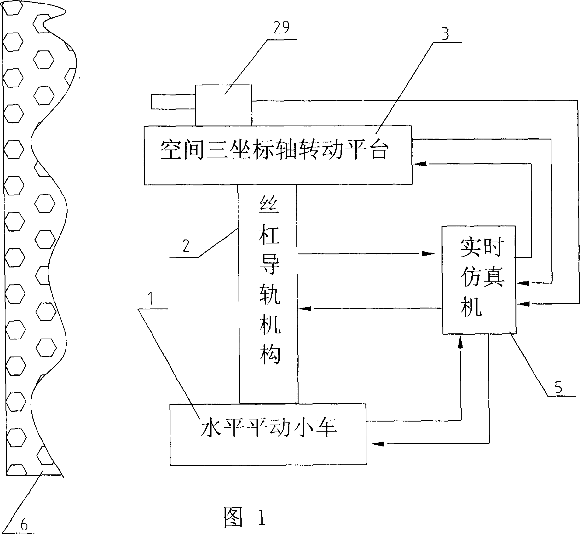
[0015] Specific Embodiment 1: The present embodiment will be specifically described below with reference to FIG. 1 . it consists of

[0016] The side surface simulates the landscape simulation sand table 6 on the surface of the target star;

[0017] The navigation camera 29 is to capture the side surface information of the scene simulation sand table 6 corresponding to the camera lens of the navigation camera 29 in real time;

[0018] The real-time simulator 5 is used to receive the information taken by the navigation camera 29 and generate position and attitude adjustment commands in real time; the described real-time simulator is provided with a pose simulation control program and an autonomous optical navigation program;

[0019] Horizontally moving the trolley 1 to receive the position and attitude adjustment commands of the real-time simulator 5, make corresponding movements in the horizontal plane, and feed back the position variation generated by the motion to the real...

specific Embodiment approach 2

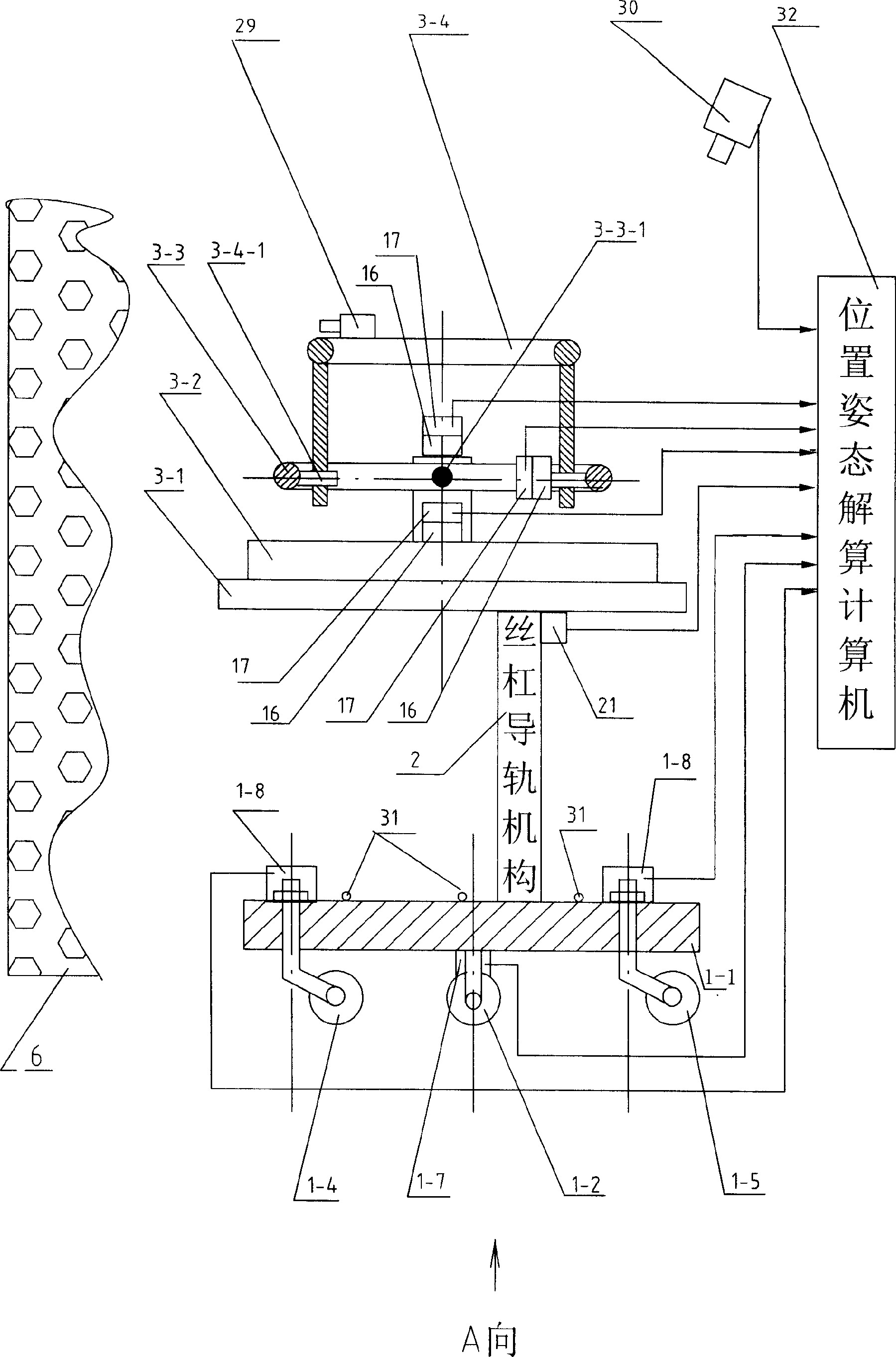
[0027] Specific implementation mode two: the following combination figure 2 This embodiment will be specifically described with FIG. 3 . The difference between this embodiment and Embodiment 1 is: the horizontal translation trolley 1 is composed of a car body platform 1-1, a first driving wheel 1-2, a second driving wheel 1-3, a first guide wheel 1-4, a second driving wheel Two guide wheels 1-5, two torque motors 1-6, two angular displacement sensors 1-7 and two deflection angle displacement sensors 1-8, the first driving wheel 1-2, the second driving wheel 1-3 Set on both sides of the vehicle body platform 1-1 and driven by a torque motor 1-6 respectively, the first guide wheel 1-4 and the second guide wheel 1-5 are respectively arranged at the front of the vehicle body platform 1-1 and the rear, a deflection angle displacement sensor 1-8 is arranged respectively between the first guide wheel 1-4 and the second guide wheel 1-5 and the car body platform 1-1, when the car body...

specific Embodiment approach 3

[0028] Specific implementation mode three: the following combination figure 2This embodiment will be specifically described. The difference between this embodiment and the second embodiment is that the space three-coordinate axis rotating platform 3 is composed of a supporting platform 3-1, a rotating platform 3-2 that is located on the supporting platform 3-1 and can rotate in the horizontal plane, and a pitching motion. frame 3-3, rolling motion frame 3-4, three torque motors 16 and three encoders 17, the supporting platform 3-1 is connected with the screw guide mechanism 2 to accept its adjustment in the height direction, The rotary table 3-2 is connected with a torque motor 16 to accept its drive, the rotary table 3-2 is connected with an encoder 17 to measure the rotation angle in real time, and the pitch motion frame 3-3 passes through the hinge shaft 3-3-1 Hinged on the upper surface of the turntable 3-2, the pitch motion frame 3-3 is connected with a torque motor 16 t...


PUM


Abstract

The simulation test device for visual navigation algorithm of soft landing of deep-space detector includes a target planet surface scene simulating sand map; a navigation camera to take the real-time information of the corresponding area; a real-time simulator to receive the information form the navigation camera to generate real-time position and posture regulating command; a horizontal translation bogie to receive the command from the real-time simulator, produce corresponding horizontal motion and feed back the portion information to the real-time simulator; a space three coordinate axes rotating platform to receive command from the real-time simulator, produce corresponding horizontal motion and feed back the portion information to the real-time simulator; and a lead screw-guide track mechanism to receive command from the real-time simulator, produce corresponding vertical transmission and feed back the portion information to the real-time simulator.

Description

technical field [0001] The invention relates to a test device for simulating the position and attitude of a probe relative to a target celestial body and the surface of a target celestial body when a deep-space probe soft-lands on a target celestial body. The device is used in the ground laboratory to verify and evaluate the performance of the autonomous optical navigation system of the deep space probe of the soft landing celestial body, and also provides an analysis experiment result for the soft landing autonomous optical navigation algorithm. Background technique [0002] With the increasing number of interplanetary exploration missions, the safe soft landing of probes on the surface of planets has become an important task and subject of deep space scientific exploration. In deep space exploration missions, due to the long communication delay between the target celestial body and the ground base station, and the relatively short duration of the process of landing on the ...

Claims


Application Information

Patent Timeline
IPC IPC(8): G01C21/00G01C21/24G01C25/00G01M99/00
Inventor 崔祜涛张泽旭崔平远徐瑞史雪岩田阳
Owner HARBIN INST OF TECH
Why Eureka
Try Eureka