Supercharge Your Innovation With Domain-Expert AI Agents!

Light-emitting device, colour light filtering structure and producing method thereof

A light-emitting device and color filter technology, applied in electroluminescent light sources, lighting devices, light sources, etc., can solve the problems of degradation of the light-emitting layer, increase in complexity, and shorten the life of color filters, so as to prolong the life and improve the finished product. The effect of rate and efficiency

Inactive Publication Date: 2006-10-18
TPO DISPLAY
View PDF3 Cites 2 Cited by
  • Summary
  • Abstract
  • Description
  • Claims
  • Application Information

AI Technical Summary

Problems solved by technology

However, spin coating is a wet process, so the transparent cover layer produced will contain a relatively high humidity, which will easily cause the life of the color filter to be shortened due to moisture absorption
Furthermore, the light-emitting layer will be degraded by the water vapor released by the color filter, which will affect the yield and life of the display
In addition, the organic light-emitting display uses pillars to adjust the height between the two substrates. During manufacture, the height of each pillar must be precisely controlled, which increases the complexity of the manufacturing process.

Method used


Image

  • Light-emitting device, colour light filtering structure and producing method thereof
  • Light-emitting device, colour light filtering structure and producing method thereof

Examples


Embodiment Construction

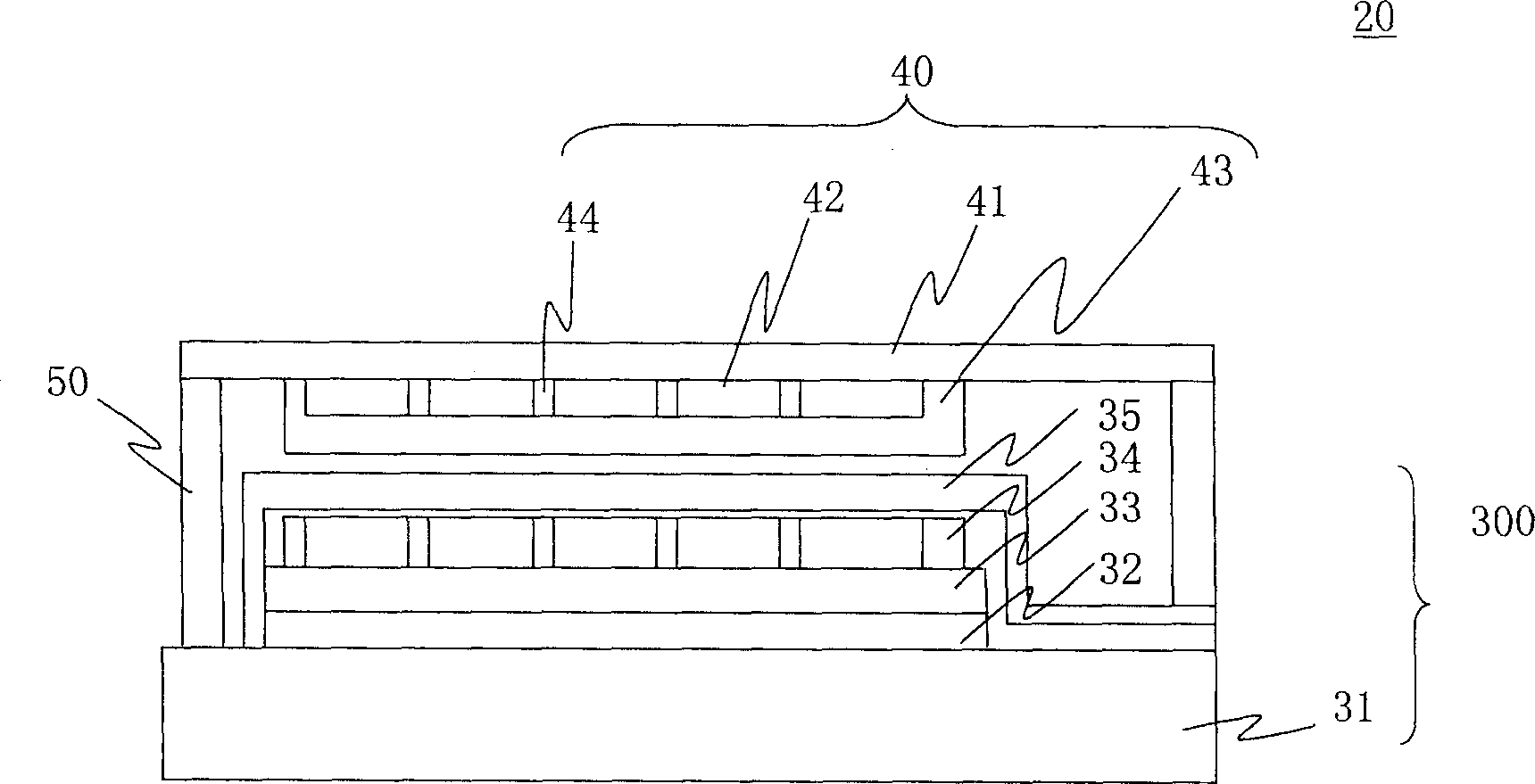
[0026] figure 2 A cross-sectional view of an embodiment of a light-emitting device of the present invention is shown. The light emitting device 20 includes: a light emitting portion 30 and a color filter structure 40 . The color filter structure 40 includes: a first substrate 41 , a filter component 42 and a first protection layer 43 . The light emitting part 30 includes: a second substrate 31 , a first electrode 32 , a light emitting layer 33 , a second electrode 34 and a second protection layer 35 . When the light emitting layer 33 is an organic light emitting layer, the light emitting device 20 is an organic electroluminescent device.

[0027] A multi-array control element (not shown in the known figure) is formed on the second substrate 31 , and each control element is composed of a switching thin film crystal, a driving thin film crystal and a capacitor. The reflectance of the second substrate 31 can be lower than that of the first electrode 32 and the second electrod...


PUM


Abstract

A luminous device consists of a color filtering structure including the first base board, a filtering component and the first protection layer; and a luminous unit. The color filtering structure is prepared as forming and covering the first protection layer being prepared by inorganic material on filtering component, combining said layer with internal side surface of the first base board to form a isolated and sealed structure for increasing service life of luminous device.

Description

technical field [0001] The invention relates to a light emitting device, in particular to an organic electroluminescence device, a color filter structure and a manufacturing method thereof. Background technique [0002] With the advent of the digital age and the popularization of the Internet, the application field of flat panel displays has successfully moved from portable medium and small products to large panels for information and household use, and even expanded to super large video applications. Currently, liquid crystal displays (LCD) It has become one of the mainstream products in the market, and organic light-emitting diode (OLED) display, due to the increasingly mature production and research and development technology in recent years and the application of a large number of nano-materials, has made an amazing breakthrough in the technology of organic light-emitting diode displays. Organic light-emitting diode displays have reached commercialization, and are moving...

Claims


Application Information

Patent Timeline
Patent Type & Authority Applications(China)
IPC IPC(8): H05B33/22H05B33/02H05B33/10
Inventor 徐湘伦
Owner TPO DISPLAY
Features
  • R&D
  • Intellectual Property
  • Life Sciences
  • Materials
  • Tech Scout
  • Unparalleled Data Quality
  • Higher Quality Content
  • 60% Fewer Hallucinations
Learn More