Electrostatic suction-type fluid discharging method and device

An electrostatic attraction and discharge device technology, which is applied to the surface coating liquid device, coating, printing, etc., can solve the problem of not taking into account the miniaturization of the nozzle and the low voltage of the driving voltage, and achieve the effect of improving reliability

Inactive Publication Date: 2006-10-18
NAT INST OF ADVANCED IND SCI & TECH
View PDF3 Cites 13 Cited by
  • Summary
  • Abstract
  • Description
  • Claims
  • Application Information

AI Technical Summary

Problems solved by technology

[0024] To sum up, in the existing fluid ejection device, there is a problem of nozzle miniaturization and high precision, and it is difficult to realize both at the same time.
Especially in the electrostatic attraction type fluid discharge device, it is considered that there is a problem that both the miniaturization of the nozzle and the reduction of the driving voltage are not compatible.

Method used


Image

  • Electrostatic suction-type fluid discharging method and device
  • Electrostatic suction-type fluid discharging method and device
  • Electrostatic suction-type fluid discharging method and device

Examples


Embodiment approach 1

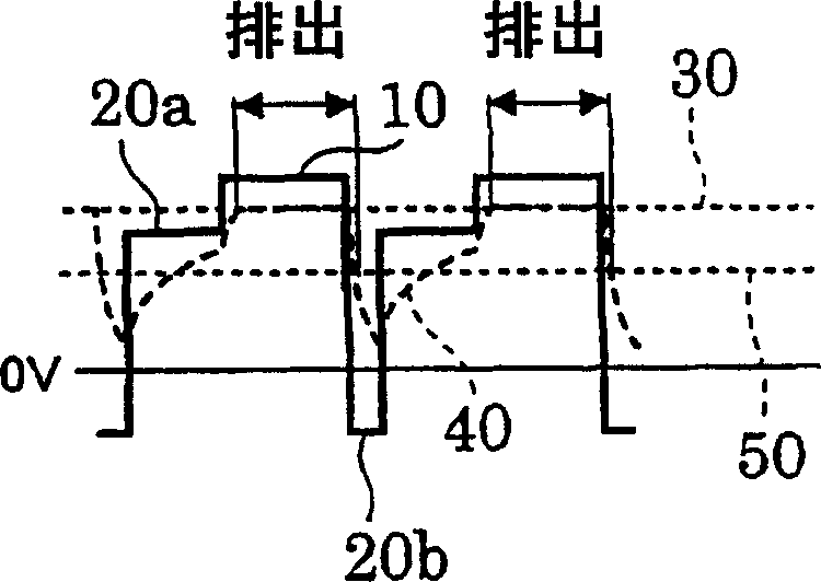
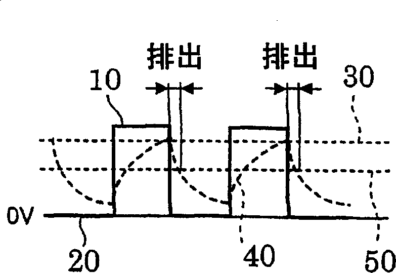
[0152] As described above, in the electrostatic attraction type fluid discharge using the local electric field, both the nozzle and the driving voltage can be made small. In this case, in order to discharge the fluid as a single flow, the method adopted is also to apply a pulse voltage between the nozzle filled with the fluid and the substrate arranged to face the tip of the nozzle, and the liquid is attracted from the tip of the nozzle to the On the substrate side, droplets are formed on the substrate.

[0153] According to this method, if the upper limit voltage (upper limit value) of the pulse voltage applied between the nozzle and the substrate is larger, the amount of fluid discharged from the nozzle will be larger; Fluid volume is low. That is, the discharge amount can be controlled by controlling the upper limit value of the pulse voltage.

[0154] However, in the case of this model, the discharge responsiveness is basically determined by the product of the resistance...

Embodiment approach 2

[0245] In the electrostatic attraction type discharge based on the fluid discharge model using a local electric field, as described above, both the nozzle diameter and the drive voltage can be reduced.

[0246] However, when using the fluid discharge model of the local electric field, the discharge responsiveness is basically determined by the time constant of the product of the resistance R of the fluid between the electrode inside the nozzle and the tip of the nozzle and the capacitance C between the tip of the nozzle and the substrate. RC lowered. Furthermore, the cell parameters of the resistance R and the capacitance C include the nozzle diameter d, and the discharge responsiveness changes with the nozzle diameter. As described above, as the nozzle diameter d decreases, the time constant RC becomes extremely large, so that the discharge responsiveness is poor, and the dischargeable polar frequency becomes low.

[0247] That is, in electrostatic attraction type fluid disc...

Embodiment approach 2-1

[0252] Figure 18 A side sectional view showing essential parts of the electrostatic attraction type fluid ejection device of this embodiment.

[0253] In such an electrostatic attraction type fluid discharge device, a substrate stage 6 functioning as an address electrode 14 is provided at a predetermined distance away from the nozzle hole of the nozzle 1 on the side facing the nozzle hole, and the substrate 13 is placed on the substrate stage 6. The purpose is to make the discharge material discharged from the nozzle hole of the nozzle 1 hit the surface of the substrate 13 stably.

[0254] Here, the substrate stage 16 is given a function as a counter substrate, but as described above, according to the present invention, due to the electric field concentration effect at the tip of the nozzle and the mirror image force induced on the counter substrate, it does not It is necessary to make the substrate conductive as in the prior art, or to provide a counter electrode on the bac...


PUM


Abstract

The discharge hole diameter of the nozzle is 0.01 to 25 μm, and the upper limit voltage (10) set to be greater than or equal to the minimum dischargeable voltage (30) as a voltage condition for starting fluid discharge is applied between the nozzle and the substrate by a voltage applying unit the pulse voltage. Before the rising edge of the pulse voltage, set the first lower limit voltage (20a) whose polarity is the same as the upper limit voltage (10) and whose absolute value is smaller than the lowest dischargeable voltage (30), and immediately after the rising edge of the pulse voltage, set A second lower limit voltage (20b) having a polarity opposite to the upper limit voltage (10). Therefore, it is possible to provide an electrostatic attraction type fluid discharge method and device, which can achieve miniaturization of nozzles, discharge of tiny fluids, high accuracy of impact position, and low voltage of driving voltage, while improving discharge start-stop characteristics and driving frequency. And it can control the pulse time of the discharge volume.

Description

technical field [0001] The present invention relates to an electrostatic attraction type fluid discharge method and device thereof, in which a fluid such as ink is charged and electrostatically attracted to discharge the fluid onto an object such as a substrate. Background technique [0002] Among the fluid ejection methods for discharging fluid such as ink onto an object (recording medium), there are generally piezoelectric methods and thermal methods that are put into practical use as inkjet printers, but there are other methods that make the discharged fluid Conductive fluid and apply an electric field to the conductive fluid to make it discharge from the nozzle hole (ink ejection hole, ejection hole) of the nozzle. [0003] As a fluid discharge device of this electrostatic attraction type (hereinafter referred to as an electrostatic attraction type fluid discharge device), for example, in Japanese Patent Publication "Patent Publication No. Sho 36-13768 (announcement date...

Claims


Application Information

Patent Timeline
Patent Type & Authority Applications(China)
IPC IPC(8): B05C5/00B41J2/06B05D1/04
Inventor 西尾茂岩下广信山本和典村田和广
Owner NAT INST OF ADVANCED IND SCI & TECH
Why Eureka
Try Eureka