

Method of dyeing or reforming injection, blow or compression moulded plastic product
A technology of injection molding and dyeing layer, which is applied in the direction of dyeing, textiles and papermaking, can solve the problems of large additives and consumption, and achieve the effects of saving energy, improving productivity, and protecting the working environment and natural environment
- Summary
- Abstract
- Description
- Claims
- Application Information
AI Technical Summary
Problems solved by technology
Method used
Image

Examples
Embodiment 1
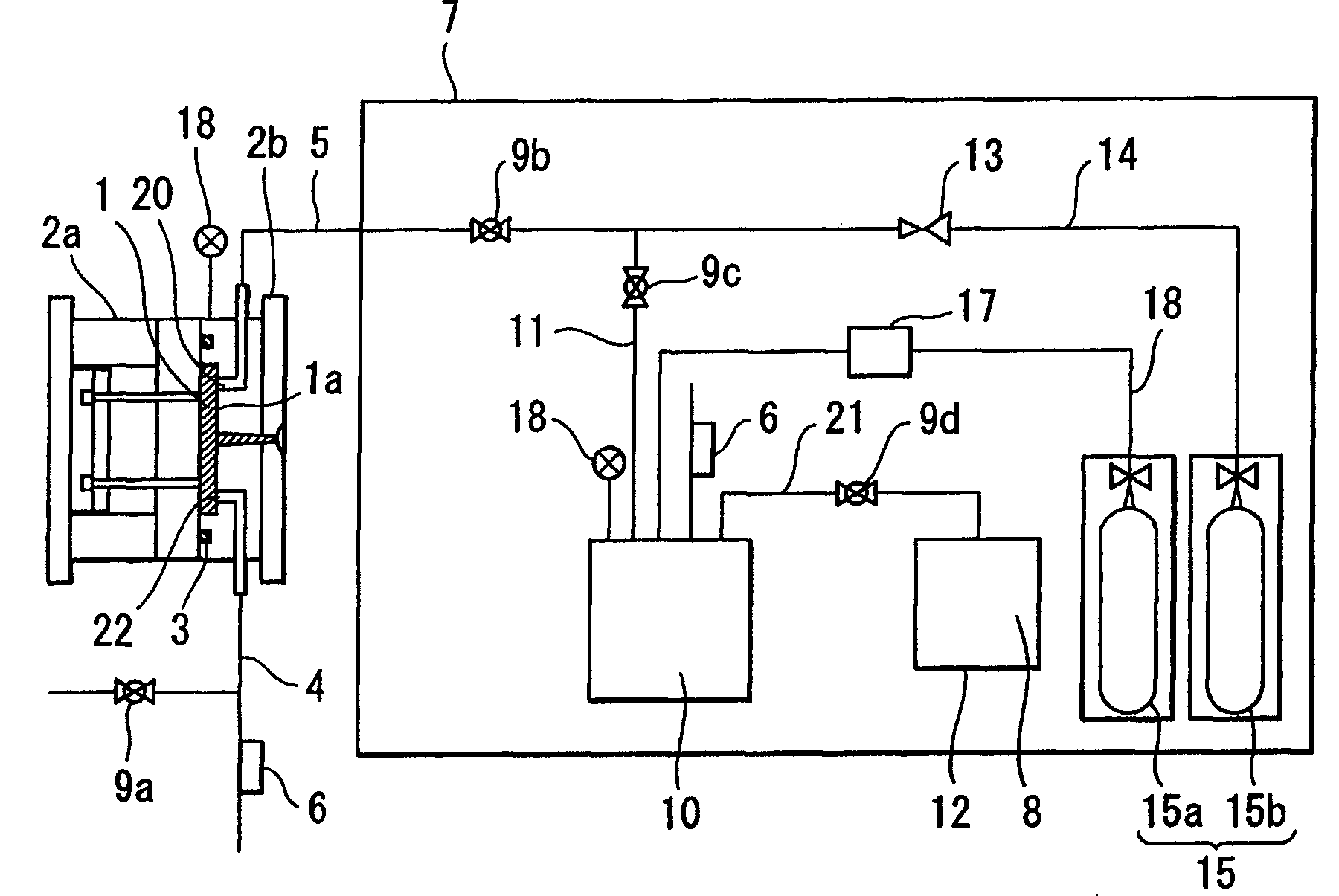
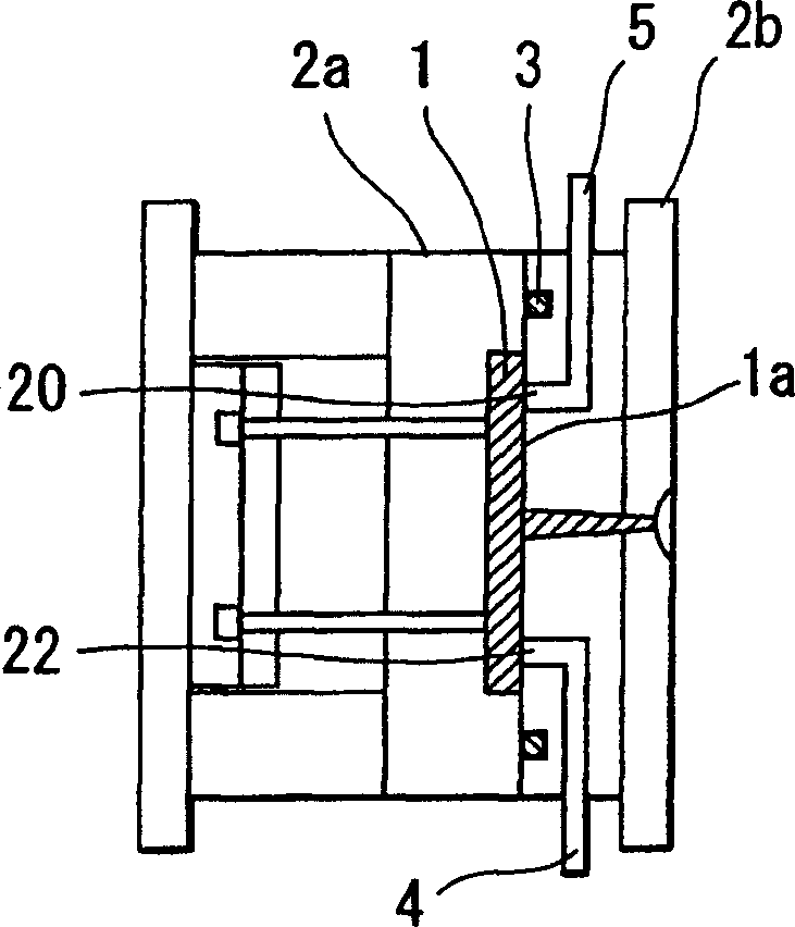
[0081] Below, refer to figure 1 and FIG. 2 illustrate an embodiment of the invention according to technical feature 1 described above.
[0082] figure 1 The mold and syringe used to practice the invention are shown. Reference numeral 1 denotes a mold cavity formed when the mold 2b on the fixed side and the mold 2a on the movable side are closely engaged with each other; O-ring; Reference numerals 9a, 9b, 9c, 9d represent electromagnetic conversion control valves for control; Reference numeral 18 represents a pressure gauge; Reference numeral 6 represents a back pressure valve, only when in the mold cavity or in each container When the air pressure is not less than the predetermined pressure level, the back pressure valve is used to discharge the gas out of the cavity. In addition, reference numeral 4 denotes an exhaust pipe connecting the back pressure valve to the exhaust port 22 for exhausting the gas in the mold cavity 1 to the outside of the cavity. Excess gas mixture ...
Embodiment 2
[0091] The molding was performed by changing the gas injection conditions used in Example 1 such as the temperature of the mixed gas of carbon dioxide and organic azo disperse dye, injection time, and injection pressure. In Example 2, the gas temperature was set at 50, 60 and 70° C., the gas injection time was set at 0.5, 1.0 and 2.0 seconds, and the injection pressure was set at 5, 10 and 15 MPa. The shaped product obtained as described above is basically affected by the mixed gas temperature, injection pressure and injection time and any one of the above parameters, and higher temperature, maximum pressure and longest injection time give excellent dyeing and reformation to the shaped product. The cross-section of each product was observed through a CCD camera zoom lens (manufactured by K.K Keyence; VH-Z150), and the degree of staining and reformation was also evaluated. The results are listed in Table 2.
Embodiment 3
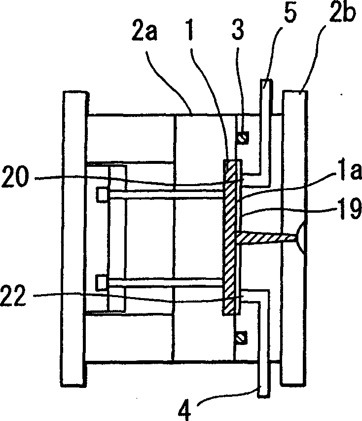
[0097] Figure 3A to Figure 3D Corresponding to the invention according to claim 4, polycarbonate (manufactured by Mitsubishi Engineering Plastic K.K.: H3000) is used as the resin. The dimensions of the shaped product obtained in this step were 32.00 mm (length), 32.0 mm (width), and 2.0 mm (thickness). In addition, the molded product was filled into cavity 1 (made of S45C material, sleeve type) with pressurized hot water at an injection pressure of 56 MPa, a filling time of 0.5 seconds, and a molten resin temperature of 280°C. In this molding method, immediately after the molten resin is filled, the pressurized state is maintained, cooled, the mold 2a on the movable side is delayed to release the mold fixing pressure, and a strong force is applied between the visible side of the surface layer and the cavity surface 1a To form a gap (A) of about 0.1mm, or in the range of 0.1mm to 1.0mm, the pressure used in Example 1 is set at any mixed gas of 15.0MPa to maintain a pressure...
PUM
 Abstract
Description
Claims
Application Information