Negative pressure sucking method for recovering waste gas and swarf for high speed drilling

A suction, negative pressure technology, used in drilling/drilling equipment, chemical instruments and methods, maintenance and safety accessories, etc.

Inactive Publication Date: 2006-11-15
上海瑞纽机械股份有限公司
View PDF0 Cites 18 Cited by
  • Summary
  • Abstract
  • Description
  • Claims
  • Application Information

AI Technical Summary

Problems solved by technology

[0003] The purpose of the present invention is to solve the problem of waste gas and chip recovery during high-speed drilling, and to provide a high-speed drilling negative pressure suction waste gas and chip recovery method

Method used


Image

  • Negative pressure sucking method for recovering waste gas and swarf for high speed drilling
  • Negative pressure sucking method for recovering waste gas and swarf for high speed drilling

Examples


Embodiment Construction

[0017] The present invention will be further described below in conjunction with the accompanying drawings and embodiments.

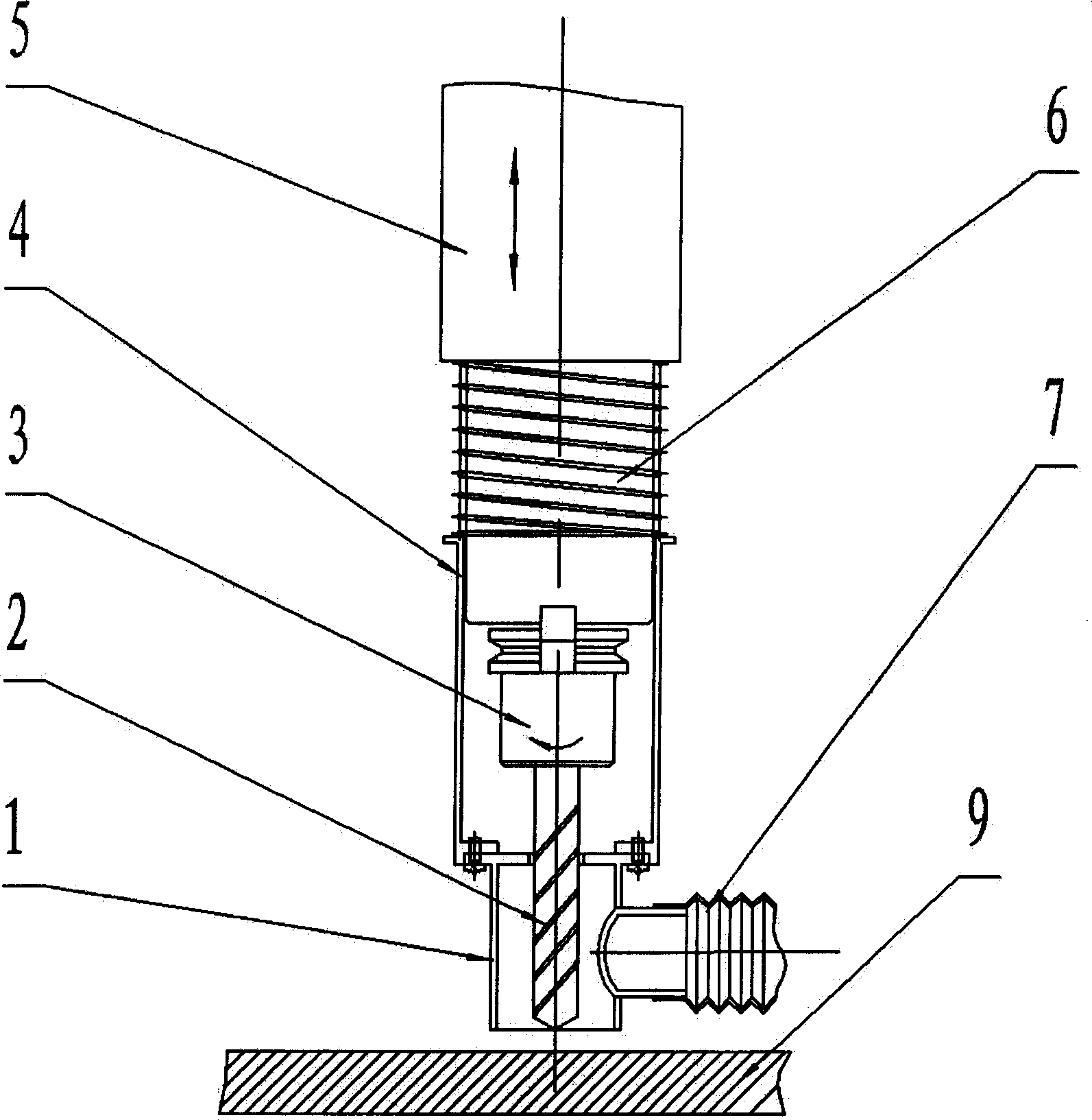
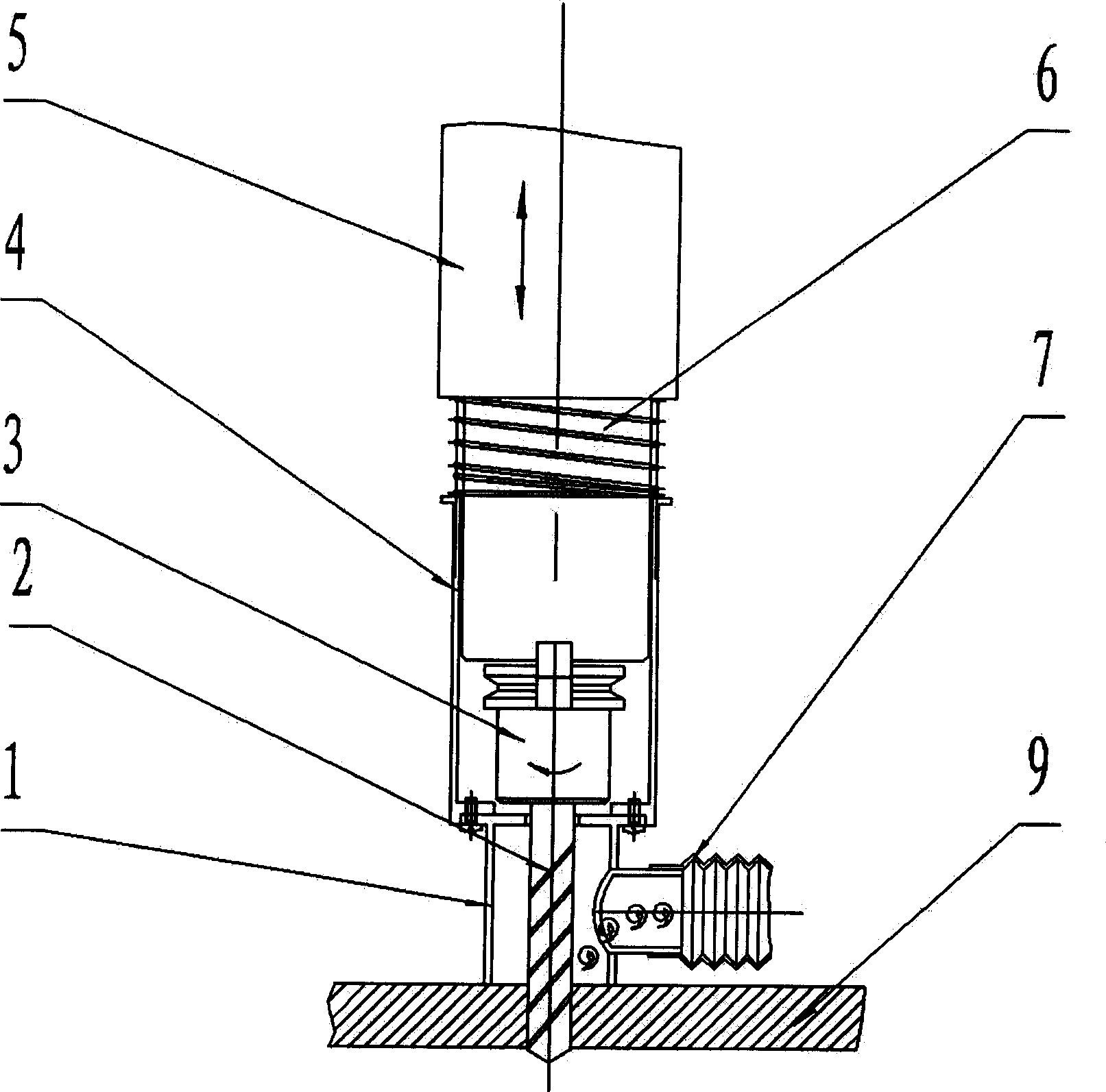
[0018] Such as figure 1 As shown, the device used for high-speed drilling negative pressure suction exhaust gas and chip recovery method includes front cylindrical sleeve 1, high-speed drill bit 2, drill chuck 3, connecting sliding sleeve 4, lifting spindle box 5, and compression spring 6 , Suction hose 7 and so on.

[0019] High-speed drilling negative pressure suction waste gas and chip recovery method, the specific implementation method is: add a cylindrical sleeve 1 to the front end of the drill shaft box 5, the diameter of the inner cavity of the cylindrical sleeve 1 is 2 to 2.5 of the diameter of the drill bit 2 times, the front end of the cylindrical sleeve 1 is adjusted to the same height as the cutting edge of the drill bit 2, and the rear end of the cylindrical sleeve 1 is connected with the connecting sliding sleeve 4, and together with the ...


PUM


Abstract

A negative-pressure suction method for recovering waste gas and chips during high-speed drilling is disclosed. A cylindrical sleeve barrel whose internal diameter is 2-2.5 times greater than the diameter of drill bit is attached to front end of drilling axle box. The height of the front end of said sleeve barrel is regulated to same as the cutting edge of drill bit and its back end is connected to a slide sleeve for moving it backward. A flexible suction tube in negative pressure state is connected to the hole on said sleeve barrel to generate airflow at 10-20 m/s for recovering waste gas and chips.

Description

technical field [0001] The invention relates to a recovery method of waste gas and cutting chips in high-speed drilling, in particular to a method of automatically removing and recovering waste gas and cutting chips by adopting a closed drilling area and a negative pressure suction method. Background technique [0002] During the high-speed drilling process, when the drill heats up and encounters oil, it will produce soot and exhaust gas. Excessive cutting speed will cause the rotating and splashing of chips and easily hurt people. This situation is an unsafe hidden danger for drilling operators. The chips splashed by drilling are scattered on the processing surface, which not only affects the processing quality but also affects the subsequent process. At present, the relatively effective way is to manually remove them. However, the manual removal method is not suitable for fully enclosed CNC automatic drilling areas. As the proportion of automation ...

Claims


Application Information

Patent Timeline
Patent Type & Authority Applications(China)
IPC IPC(8): B23B47/00B08B15/00B23B47/34B23Q11/00
CPCY02P70/10
Inventor 韩世卓贺明健马伟民
Owner 上海瑞纽机械股份有限公司
Why Eureka
Try Eureka