
Laser pulse stretching and compression device

A laser pulse and compression device technology, applied in the field of strong laser, can solve problems such as low conversion efficiency and complex structure

Inactive Publication Date: 2006-11-29
SHANGHAI INST OF OPTICS & FINE MECHANICS CHINESE ACAD OF SCI
View PDF0 Cites 27 Cited by
  • Summary
  • Abstract
  • Description
  • Claims
  • Application Information

AI Technical Summary

Problems solved by technology

[0008] It can solve the problems of low conversion efficiency and complex structure in the use of nonlinear crystal stretching pulse technology;

Method used


Image

  • Laser pulse stretching and compression device
  • Laser pulse stretching and compression device
  • Laser pulse stretching and compression device

Examples


Embodiment Construction

[0038] The present invention will be further described below in conjunction with the embodiments and accompanying drawings, but the protection scope of the present invention should not be limited thereby.

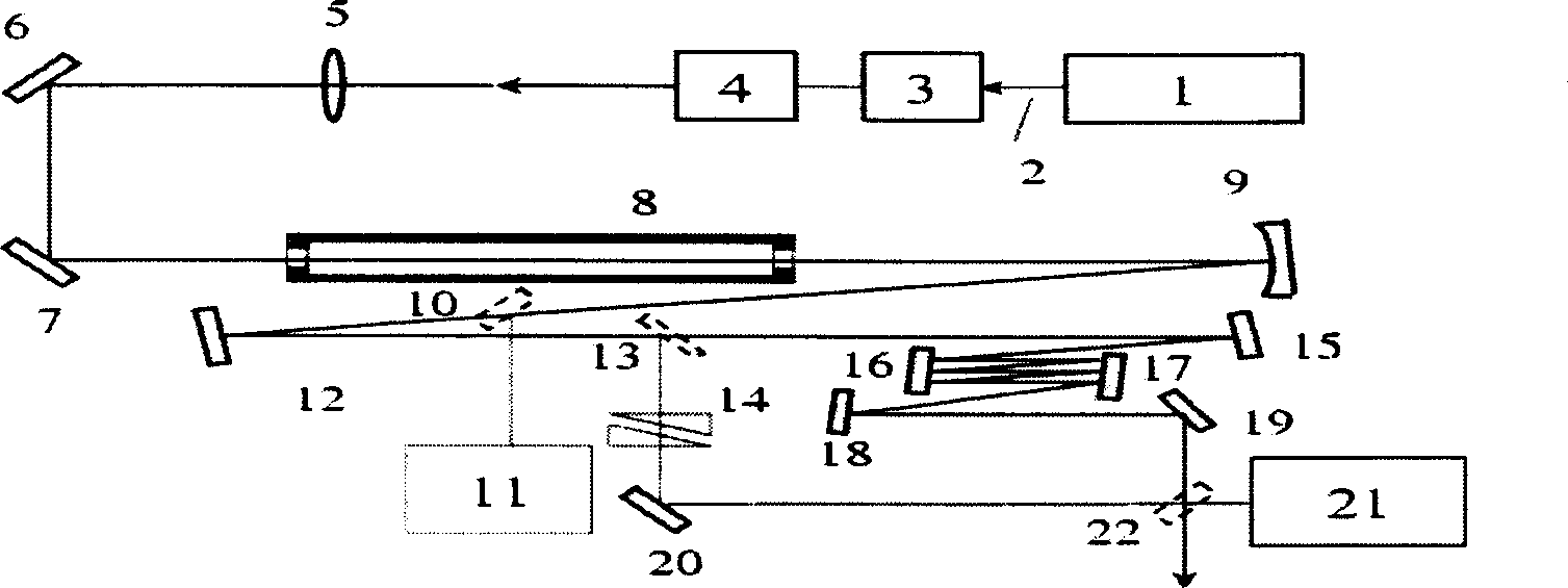
[0039]see first figure 1 , figure 1 It is a structural schematic diagram of an embodiment of the intense laser pulse stretching and compression device of the present invention. As can be seen from the figure, the laser pulse stretching and compression device of the present invention is characterized in that it consists of an ultrashort pulse laser 1, a chirp control system 3, an energy control system 4, a nonlinear action system, a dispersion compensation system and a test system. The output direction of the laser beam 2 of the ultrashort pulse laser 1 is sequentially a chirp control system 3, an energy control system 4, a nonlinear action system composed of a focusing lens 5, a nonlinear medium 8 and a concave reflector 9, and the The dispersion compensation system compr...


PUM


Abstract

This invention relates to a laser pulse expansion and compression device charactering that it is composed of a super-short pulse laser, a chirp control system, an energy control system, a non-linear action system, a dispersion compensation system and a test system, which can either expand spectrums and compress pulses or compress spectrums and expand pulses.

Description

technical field [0001] The invention relates to a strong laser, in particular to a laser pulse stretching and compression device. The device can be applied to biological, physical and chemical research fields such as high-intensity ultrafast laser technology, ultrashort pulse laser micromachining and pump-probe technology. Background technique [0002] In the past few decades, femtosecond pulsed laser technology has achieved tremendous development. Using mode-locking technology and chirped pulse amplification (CPA) technology for titanium-doped sapphire (Ti: sapphire) laser system, it has been possible to obtain tens of femtoseconds, terawatt (TW) level desktop ultra-powerful super short laser pulses. This ultra-intense and ultra-short laser pulse is an important tool in many fundamental studies of high-field laser physics, such as high-order harmonics, plasma channels, and attosecond pulse generation. Researches such as femtosecond chemistry, biomedicine, pump-probe and ...

Claims


Application Information

Patent Timeline
IPC IPC(8): H01S3/00G02F1/00G02F1/35G02B5/00
Inventor 刘军陈晓伟李小芳曾志男李儒新戴君
Owner SHANGHAI INST OF OPTICS & FINE MECHANICS CHINESE ACAD OF SCI
Learn More