Control circuit of synchronization switching power converter

A technology of power converter and control circuit, which is applied in output power conversion device, conversion of DC power input to DC power output, control/regulation system, etc., can solve the problem that power converter is not easy to switch and signal synchronization.

Active Publication Date: 2006-12-06
SYST GEN
View PDF3 Cites 9 Cited by
  • Summary
  • Abstract
  • Description
  • Claims
  • Application Information

AI Technical Summary

Problems solved by technology

[0003] In the above-mentioned conventional technology, since the switching frequency of the switching signal changes according to the change of the load,

Method used


Image

  • Control circuit of synchronization switching power converter
  • Control circuit of synchronization switching power converter
  • Control circuit of synchronization switching power converter

Examples


Embodiment Construction

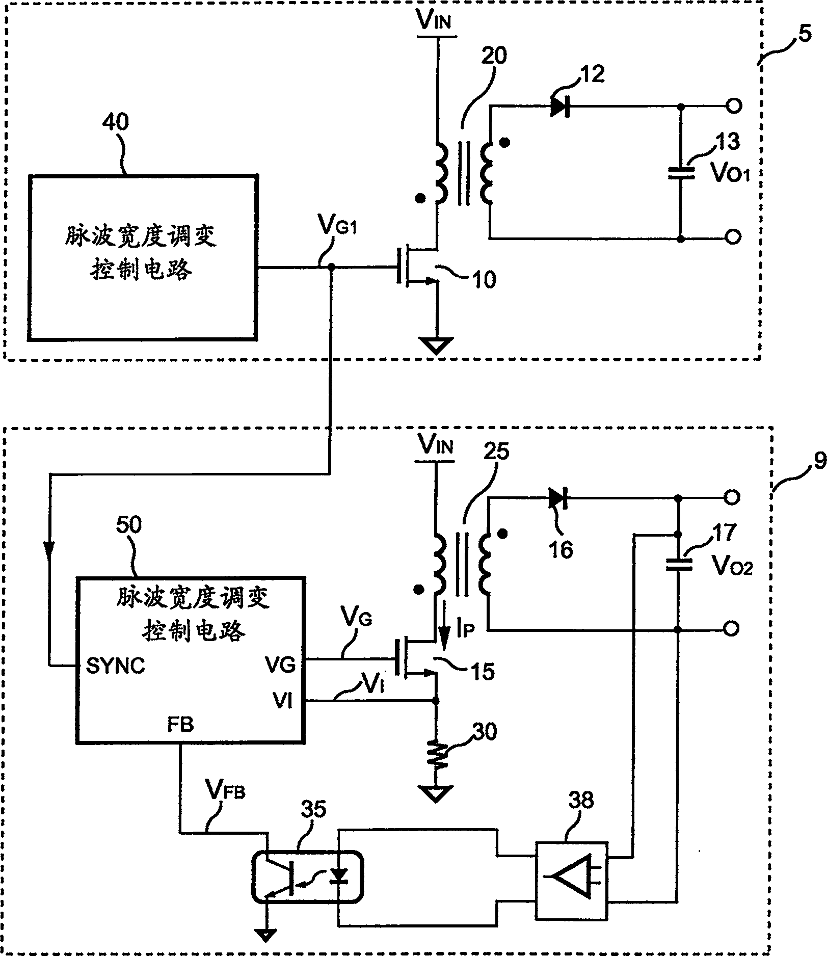
[0085] see figure 1 , which is a power converter with synchronous switching in the present invention. As shown in the figure, a first power converter 5 includes a transformer 20 coupled to an input voltage V IN and a ground terminal to generate an output voltage V O1 . A transistor 10 is connected in series with the primary side of the transformer 20 and the ground terminal. A rectifier 12 is coupled to the secondary side of the transformer 20 . A filter capacitor 13 is coupled to the secondary side of the rectifier 12 and the transformer 20 . A pulse width modulation (Pulse WidthModulation, PWM) control circuit 40 of the first power converter 5, which generates a switching signal V G1 and sent to the transistor 10 to switch the transformer 20 and adjust the output voltage V O1 . At the same time, the switching signal V G1 It is also transmitted to a synchronous input terminal SYNC of a pulse width modulation (PulseWidth Modulation, PWM) control circuit 50 of a second ...


PUM


Abstract

The disclosed synchro switching control circuit in use for switching power converter with changeable frequencies includes following parts: a first circuit in use for generating a first signal based on an input synchronous signal; being coupled to the first circuit, a second circuit in use for generating a second signal based on frequency of the first signal, and synchronous operation is allowed only when the first signal is operated at a specific frequency range; being connected to the first circuit and the second circuit, an oscillation circuit in use for receiving first signal and second signal, and then generating an oscillation signal; the oscillation signal in use for enabling a switching signal of power converter, therefore the switching signal is synchronous to the input synchronization signal based on enabled second signal, otherwise operation of the switching signal will not be restricted.

Description

Technical field: [0001] The present invention relates to a power converter, in particular to a control circuit of a switching power converter. Background technique: [0002] By the way, today's power converters are used to convert an unregulated power source into a regulated voltage source and a current source. The power converter adjusts by generating a switching signal through the control circuit. The duty cycle of the switching signal is adjusted according to the output of the power converter, and the switching frequency of the switching signal is usually determined by the control circuit of the power converter, so when a system is configured with more than one power converter, then The switching signals must be synchronized to reduce switching noise and electromagnetic interference (ElectroMagnetic Interference, EMI). However, recent developments have proposed many pulse width modulation (Pulse Width Modulation, PWM) control circuits that save power loss, such as the U...

Claims


Application Information

Patent Timeline
IPC IPC(8): H02M3/335G05F1/56
Inventor 陈振松杨大勇吕瑞鸿
Owner SYST GEN
Why Eureka
Try Eureka