Constant power control method and device of electronic ballast

A technology of constant power control and electronic ballast, which is applied in the direction of lighting devices, electric light sources, electrical components, etc., and can solve the problems of complex circuits and high costs

Inactive Publication Date: 2006-12-06
ZHEJIANG UNIV
View PDF0 Cites 3 Cited by
  • Summary
  • Abstract
  • Description
  • Claims
  • Application Information

AI Technical Summary

Problems solved by technology

This solution is complex and expensive

Method used


Image

  • Constant power control method and device of electronic ballast
  • Constant power control method and device of electronic ballast
  • Constant power control method and device of electronic ballast

Examples


Embodiment Construction

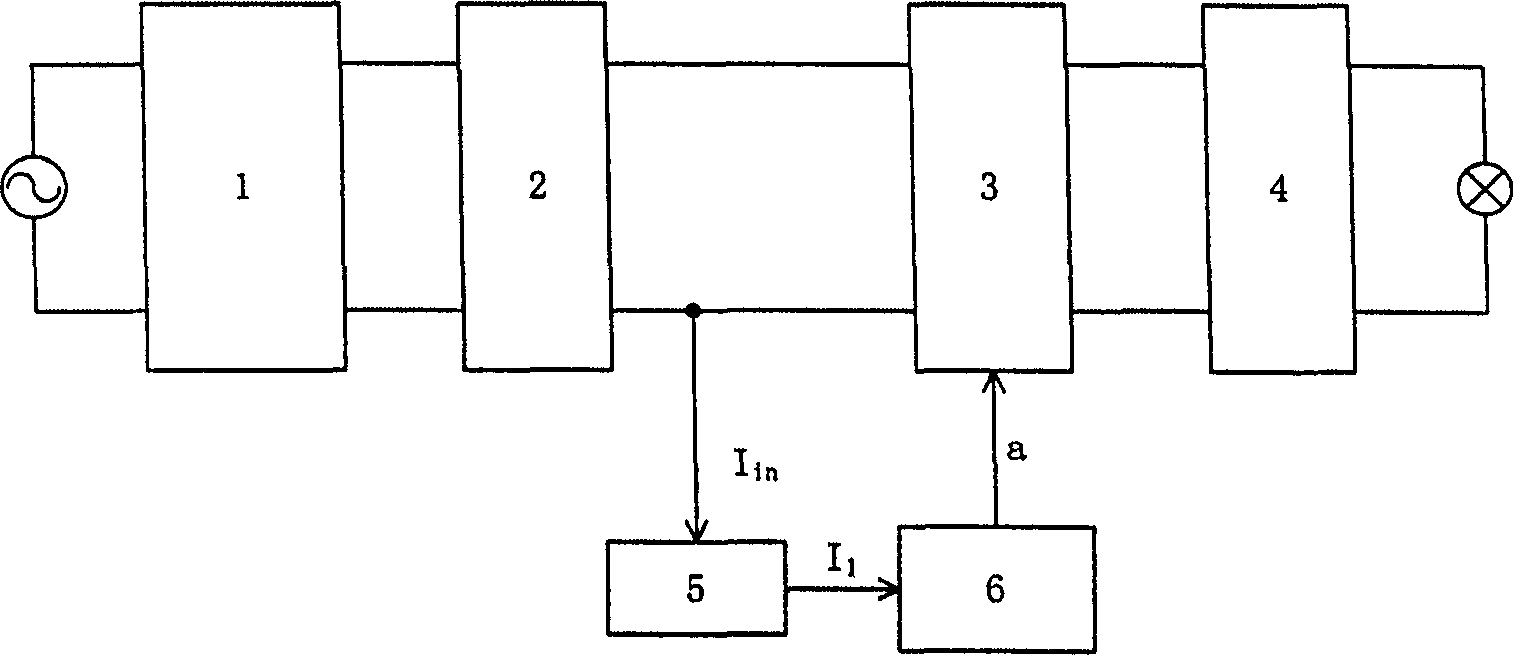
[0024] refer to figure 1 The main power part of the electronic ballast includes an electromagnetic interference (EMI) filter unit 1 , an AC / DC unit 2 , a DC / DC unit 3 and a DC / AC unit 4 . The input is AC power. The DC / DC unit 3 controls the current of the high-intensity gas discharge lamp, and the specific control method is as follows: the current detection unit 5 detects the output current I of the AC / DC unit 2 in , after transformation, the variable current I is obtained 1 ; In the control unit 6, the variable current I 1 Compared with the preset current value, the control signal a of the DC / DC unit 3 is generated; the DC / DC unit 3 generates the driving signal of its switch tube according to the control signal a, and realizes the control of the DC / DC unit 3. The input The current is equal to the preset current value.

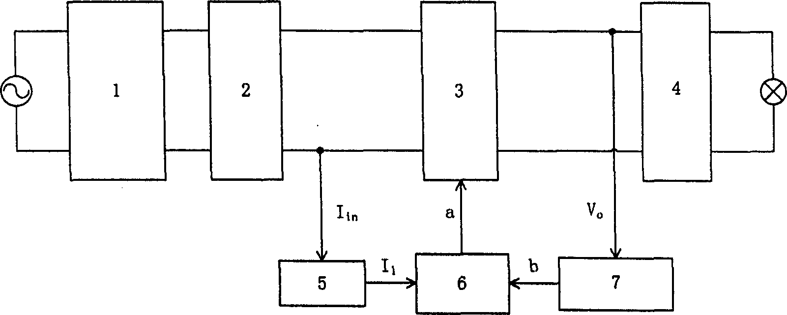
[0025] refer to figure 2 ,and figure 1 Compared with it, an output voltage detection and transformation unit 7 is added, and the purpose of voltage det...


PUM


Abstract

The method comprises: presetting a current value for the high intensity gas discharge lamp; detecting the output current from AC/DC converter; comparing the converted variable current with the preset current value to generate a control signal for the AC/DC converter; generating a driving signal to switch tube, and controlling its input current to equal to the preset value.

Description

technical field [0001] The invention relates to an electronic ballast, in particular to a low-cost, high-performance power control method and device for an electronic ballast. Background technique [0002] High-intensity gas discharge lamps (referred to as lamps) have been widely used for their good luminous efficiency, long life and good color rendering. However, high-intensity gas discharge lamps must be used with ballasts to work stably. Traditional inductive ballasts have many shortcomings such as large size, bulkiness, low efficiency, consumption of non-ferrous metals such as copper, and poor control performance; and these various shortcomings of inductive ballasts can be greatly improved in electronic ballasts. Good solution. [0003] Electronic ballasts can achieve various complex control functions, especially the constant power control method can be used to ensure constant lamp power, stabilize light output, improve lighting effects, and prolong lamp life. This is...

Claims


Application Information

Patent Timeline
Patent Type & Authority Applications(China)
IPC IPC(8): H05B41/14
Inventor 陈敏许建炳梁伟霞钱照明
Owner ZHEJIANG UNIV
Why Eureka
Try Eureka