Housing cup for an electronic component with integrated cooling body

A technology for electronic components and cooling bodies, applied in electrical components, resistor parts, capacitor parts and other directions, can solve the problems of high installation costs of cooling bodies, increase in volume of electronic devices, high installation costs, etc., and achieve higher manufacturing costs. The effect of eliminating additional costs and reducing costs

Inactive Publication Date: 2006-12-06
SIEMENS AG
View PDF1 Cites 0 Cited by
  • Summary
  • Abstract
  • Description
  • Claims
  • Application Information

AI Technical Summary

Problems solved by technology

[0006] It is disadvantageous to increase the volume of electronic devices due to higher material requirements, and it is also disadvantageous to use parallel circuits with a higher number of electronic devices due to higher manufacturing costs and higher installation costs
Even the subsequent mounting of the cooling body on the housing of the electronic components is disadvantageous due to the relatively high installation effort

Method used


Image

  • Housing cup for an electronic component with integrated cooling body
  • Housing cup for an electronic component with integrated cooling body
  • Housing cup for an electronic component with integrated cooling body

Examples


Embodiment Construction

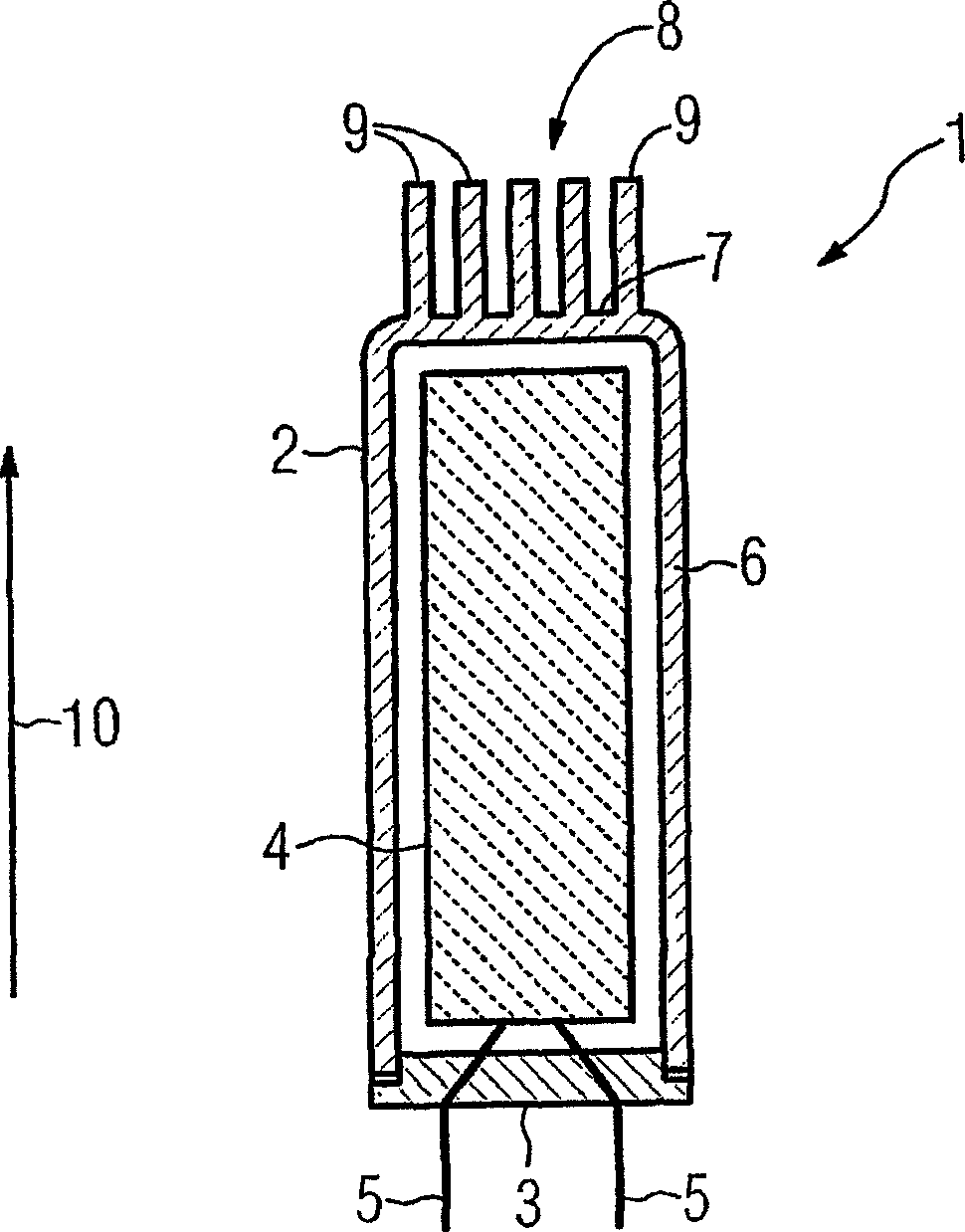
[0029] figure 1 The housing of the electronic device 1 is shown schematically, which comprises a cylindrical cup 2 closed by a housing cover 3 . Inside the housing formed by the cup 2 and the housing cover 3 is an electronic component 4 , which is contactable via two contacts 5 in the form of wires leading out through the housing cover 3 .

[0030] The cup 2 has a tubular side wall 6 which is closed on the front side opposite the housing cover 3 by a cup base 7 integral with the side wall 6 . The cup bottom 7 forms the basic surface of the heat sink 8 integrated with the cup 2 . The heat sink 8 also includes a number of projections 9 which stand up on the outer surface of the cup base 7 in the axial direction 10 of the cup 2 and are at a certain distance from one another.

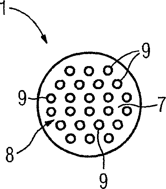
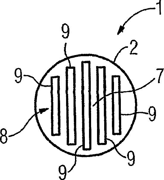
[0031] figure 2 and 3 Two different configurations of the projections 9 of the cup bottom 7 as viewed towards the axial direction 10 are shown. according to figure 2 The protrusions 9 are configured...


PUM


Abstract

According to the invention, the cooling capacity of an electronic component may be improved with simple means, whereby the electronic component (4) is provided with a housing cup (2), produced by an extrusion method, the cup base (7) of which is formed to give a cooling body (8), integral with the housing cup (2).

Description

technical field [0001] The invention relates to a housing for electronic components, which basically consists of a cup. Background technique [0002] During the operation of electronic components, depending on their particular field of application, high power losses in the form of heat have hitherto occurred. Higher losses lead to higher thermal loads. Thermal loads have a decisive effect on reducing the lifetime of the electronic components, so this heat must be dissipated via the housing of the electronic components. Therefore, the thermal conductivity of the shell essentially determines the life of the electronic components, the specific application field and the layout design of the electronic components. In general, better heat transfer means increased current carrying capacity or allows for higher ambient temperatures. In order to reduce the temperature rise of electronic components, their heat exchange area is partially increased, or distributed in electronic circu...

Claims


Application Information

Patent Timeline
Patent Type & Authority Applications(China)
IPC IPC(8): H05K7/20H01G9/08H01G2/08H01M8/02H01M8/12H01C1/084
CPCH01G4/38H01G4/32H01G9/08H01G2/08
Inventor 洛撒·里根富斯
Owner SIEMENS AG
Why Eureka
Try Eureka