Plasma display panel, method of manufacturing the same, and composition of partitions thereof

A display panel and plasma technology, applied in the direction of alternating current plasma display panels, cold cathode manufacturing, electrode system manufacturing, etc., can solve the problems of color temperature deterioration, image quality deterioration, panel appearance damage, etc.

Inactive Publication Date: 2006-12-13
LG ELECTRONICS INC
View PDF0 Cites 9 Cited by
  • Summary
  • Abstract
  • Description
  • Claims
  • Application Information

AI Technical Summary

Problems solved by technology

[0013] Because of the yellow discoloration of the spacer, the color temperature of white light of visible rays displayed on the front panel deteriorates, so that the image quality deteriorates and the appearance of the panel is impaired

Method used


Image

  • Plasma display panel, method of manufacturing the same, and composition of partitions thereof
  • Plasma display panel, method of manufacturing the same, and composition of partitions thereof
  • Plasma display panel, method of manufacturing the same, and composition of partitions thereof

Examples


Embodiment Construction

[0032] Preferred embodiments of the plasma display panel, its manufacturing method and the material for the spacer of the plasma display panel of the present invention are described in detail below, in Figures 1 to 9K An example of it is shown in .

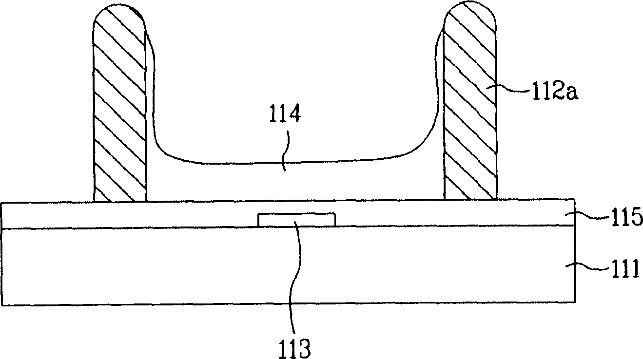
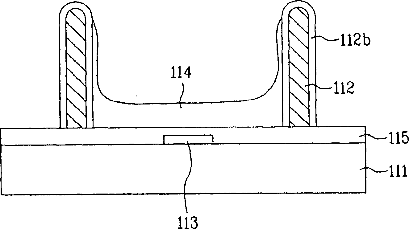
[0033] figure 2 is a cross-sectional view schematically illustrating the rear substrate of the plasma display panel according to the first preferred embodiment of the present invention.

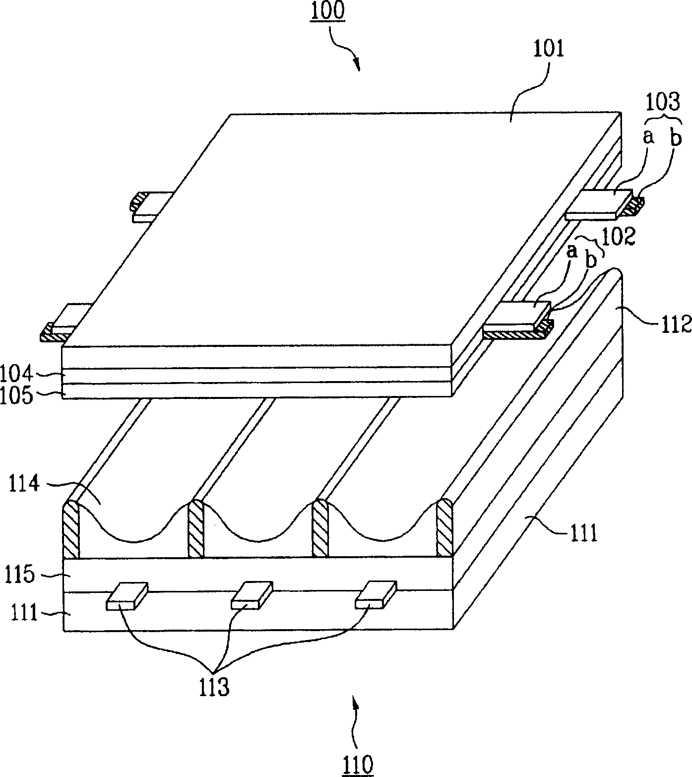
[0034] The front substrate of the plasma display panel according to this preferred embodiment of the present invention has the same structure as the front substrate of the existing plasma display panel, so that a plurality of pairs of sustain electrodes forming scan electrodes and sustain electrode pairs are arranged in the existing plasma display panel. The front substrate of the display panel is on a front glass 101 which is a display surface in which an image is displayed. In the rear substrate, a plurality of address electrodes 113 are ar...


PUM


Abstract

A plasma display panel includes an upper plate having a sustain electrode, a lower plate having an address electrode, and a partition formed between the upper plate and the lower plate and having an inorganic ion exchanger. The yellow discoloration of the partition is prevented to improve color brightness and light permeability.

Description

[0001] This application claims the benefit of Korean Patent Application No. P2005-0036031 filed on Apr. 29, 2005, which is hereby incorporated by reference in its entirety. technical field [0002] The present invention relates to a plasma display panel, and more particularly, to a plasma display panel in which spacers generated when forming electrodes are prevented from being discolored to yellow, and a method of manufacturing the same. Background technique [0003] Generally, in a plasma display panel, a spacer formed between a front substrate and a rear substrate separates unit cells. [0004] Each unit cell is filled with a main discharge gas such as neon gas, helium gas or a mixed gas of neon gas and helium gas and an inert gas including a small amount of xenon gas. When an electrical discharge is generated due to the application of a high-frequency voltage, the inert gas generates vacuum ultraviolet rays to irradiate the fluorescent material, so that an image is displa...

Claims


Application Information

Patent Timeline
Patent Type & Authority Applications(China)
IPC IPC(8): H01J17/49H01J17/02H01J17/04H01J17/16H01J9/24C03C6/00H01J9/02H01J11/12H01J11/22H01J11/24H01J11/26H01J11/34H01J11/36
CPCH01J11/36H01J11/12H01J9/242H01J2211/366
Inventor 申正撤
Owner LG ELECTRONICS INC
Why Eureka
Try Eureka