
Vibration generating device for portable electronic apparatus

A technology of vibration power generation and electronic equipment, which is applied to battery circuit devices, electromechanical devices, circuit devices, etc., and can solve problems such as inability to be built directly, low power generation efficiency, and large volume

Inactive Publication Date: 2006-12-13
深圳市杰特电信控股有限公司
View PDF1 Cites 37 Cited by
  • Summary
  • Abstract
  • Description
  • Claims
  • Application Information

AI Technical Summary

Problems solved by technology

This kind of vibrating charger mainly utilizes the energy of the vibrating mechanism of the vehicle during driving to generate power. Its volume is generally too large to be directly built into smaller portable electronic devices, and the permanent magnet in this vibrating charger passes through Spring connection, when the external vibration is strong, the permanent magnet can produce a large movement and generate current. In addition, the utility model device only rectifies through an effective diode, and can only use half of one operating cycle of the permanent magnet. Power generation, and the power generation process is interrupted, the efficiency of power generation is not high, only half of the mechanical energy of the permanent magnet movement participates in power generation

Method used


Image

  • Vibration generating device for portable electronic apparatus
  • Vibration generating device for portable electronic apparatus
  • Vibration generating device for portable electronic apparatus

Examples


Embodiment 1

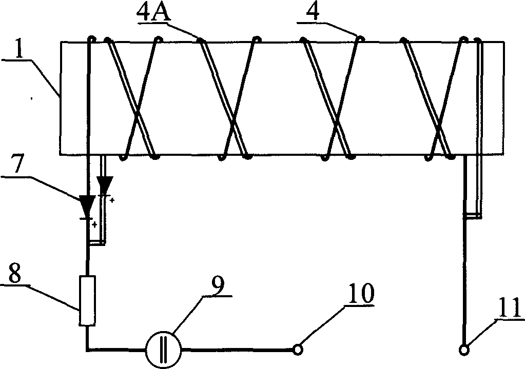
[0023] Example 1: Double winding group vibration power generation and charging device

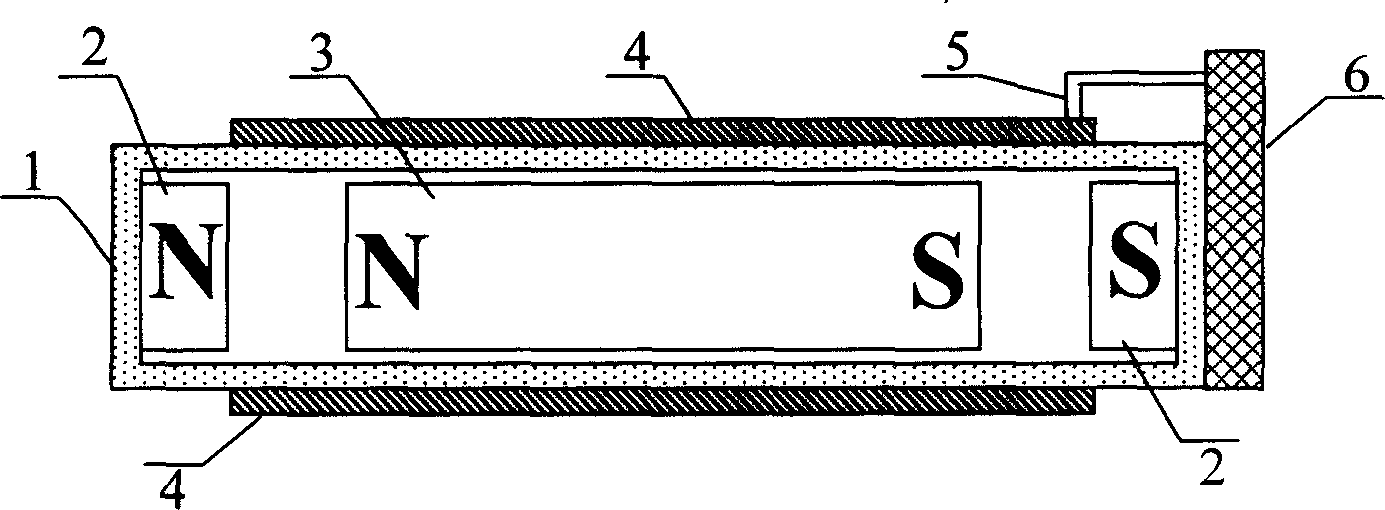
[0024] Design a vibration power generation and charging device of the present invention in the mobile phone, add a motion chamber made of non-metallic material on the mobile phone, its internal thickness is 2 millimeters, length and width are equivalent to the battery of the mobile phone, the motion chamber is placed under the battery, A sheet-shaped movable permanent magnet that just can move in the movement cavity is loaded in the movement cavity. For other parameters of the device, refer to the foregoing description of this embodiment.

[0025] See figure 2, Two winding coils (4, 4A) with different winding directions are placed on the outer wall of the exercise chamber, and two wires drawn from the two winding coils at one end of the exercise chamber are connected in series with one with the same polarity direction Diode (7), because when the movable permanent magnet moves, the directi...

Embodiment 2

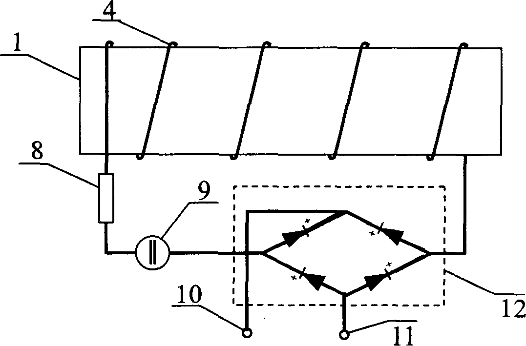
[0026] Embodiment 2: bridge rectification vibration power generation charging device

[0027] See image 3 , add a bridge rectifier component on the leading wire of the coil of the single winding group, so that the currents in different directions generated in the coil of the winding group are processed into the current of the same direction and sent to the charging device, plus a voltage stabilizing capacitor ( 9) The voltage stabilizing function ensures that the charging current is a stable direct current.


PUM


Abstract

The invention discloses a vibration generating device of portable electronic equipment, which comprises the following parts: permanent magnet, winding group, moving cavity and charging device, wherein the winding group winds the outer surface of moving cavity, whose two ends fix permanent magnet in the moving cavity movably; the moving permanent magnet moves reciprocally in the moving cavity acted by outer vibration and fixed permanent magnet repulsion, which produces relative movement for winding group; the induction current is generated through cutting magnetic line in the winding group, which provides DC power to charge battery after passing diode and commutating circuit. The invention improves converting efficiency of generating device in the vibration generating course, which reduces bulk greatly to place vibration generating device in the portable electronic equipment conveniently.

Description

【Technical field】 [0001] The present invention relates to a power generation device, in particular to a vibration power generation and charging device that can be built into a portable electronic device. 【Background technique】 [0002] A large number of portable electronic devices such as mobile phones, PDAs, MP3 players, and electric toys all use rechargeable batteries, but in many cases, when the rechargeable batteries of these electronic devices are exhausted, they cannot find a rechargeable power source in time. On the one hand, with the development of science and technology, the development trend of various fashionable electronic products is increasingly rich in functions, resulting in an increasing demand for power supply. On the other hand, for the convenience of portability, manufacturers and consumers are pursuing smaller The size and lighter weight make the design of the power supply a major bottleneck in the development of this type of product. Therefore, designi...

Claims


Application Information

Patent Timeline
IPC IPC(8): H02K35/02H02J7/32
CPCY02B40/90Y02B40/00
Inventor 向东
Owner 深圳市杰特电信控股有限公司
Learn More