Hydrogen generating apparatus

A generation device and generation unit technology, applied in the direction of hydrogen, electrochemical generators, fuel cells, etc., can solve problems such as poor response performance, achieve the effects of ensuring uniformity, excellent response performance, and reducing the number of catalysts

Inactive Publication Date: 2006-12-13
PANASONIC CORP
View PDF1 Cites 6 Cited by
  • Summary
  • Abstract
  • Description
  • Claims
  • Application Information

AI Technical Summary

Problems solved by technology

Therefore, when it is necessary to increase the supply amount of the reformed gas supplied to the fuel cell according to the increase in the power consumption of the load, it takes a long time until the temperature distribution inside the hydrogen generator 400 becomes the optimum temperature distribution. Therefore, there is a problem of poor responsiveness

Method used


Image

  • Hydrogen generating apparatus
  • Hydrogen generating apparatus
  • Hydrogen generating apparatus

Examples


Embodiment Construction

[0145] best practice

[0146] The best mode for carrying out the present invention will be described in detail below with reference to the accompanying drawings.

[0147] Embodiment 1

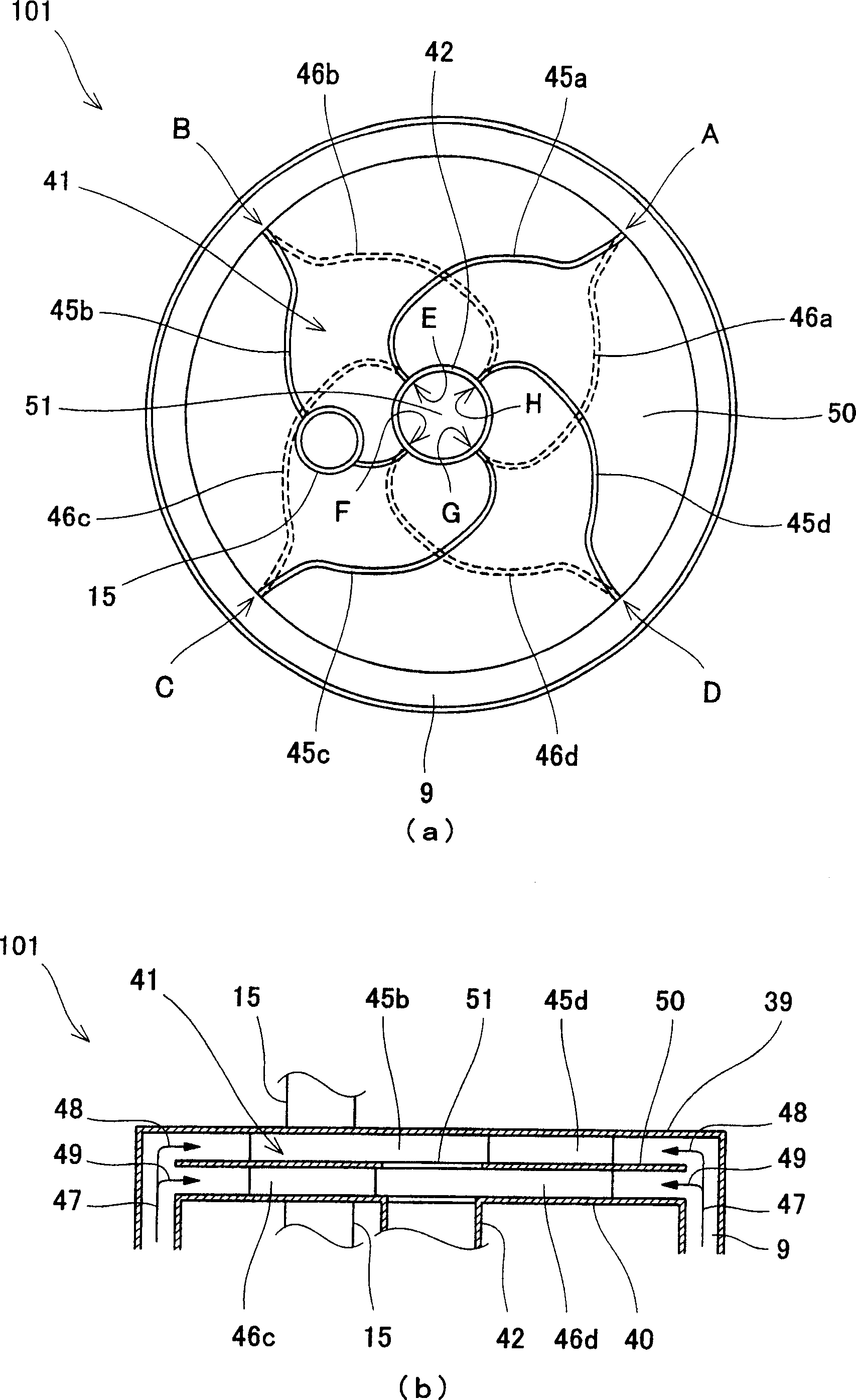
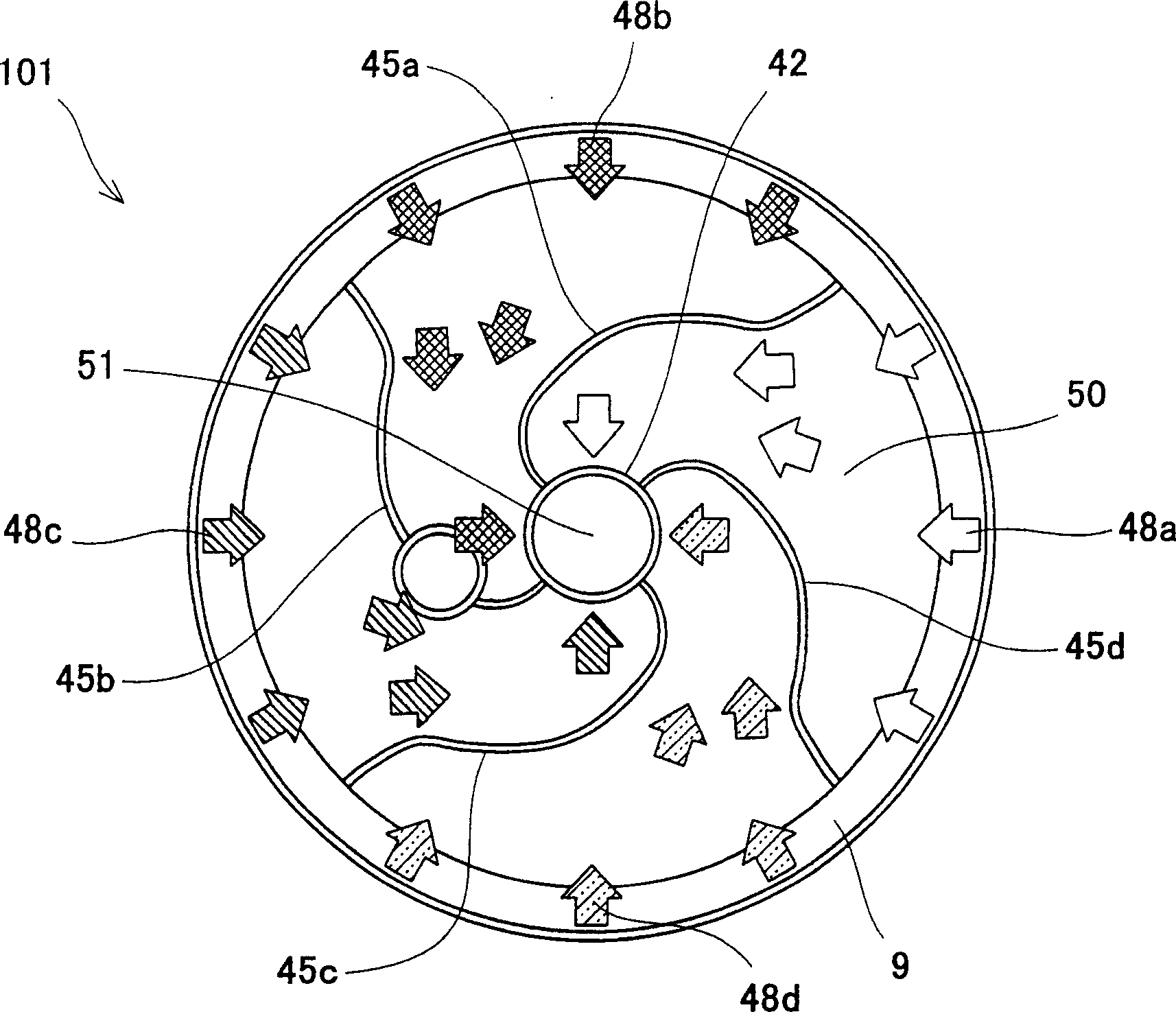
[0148] In Embodiment 1 of the present invention, a disc-shaped space is used to connect an evaporator for evaporating supplied water and mixing it with raw materials to generate mixed gas, and a reaction for steam reforming reaction for generating reformed gas. In the section, a gas mixer is arranged in the disc-shaped space to improve the mixing state of gas mixing in the horizontal direction.

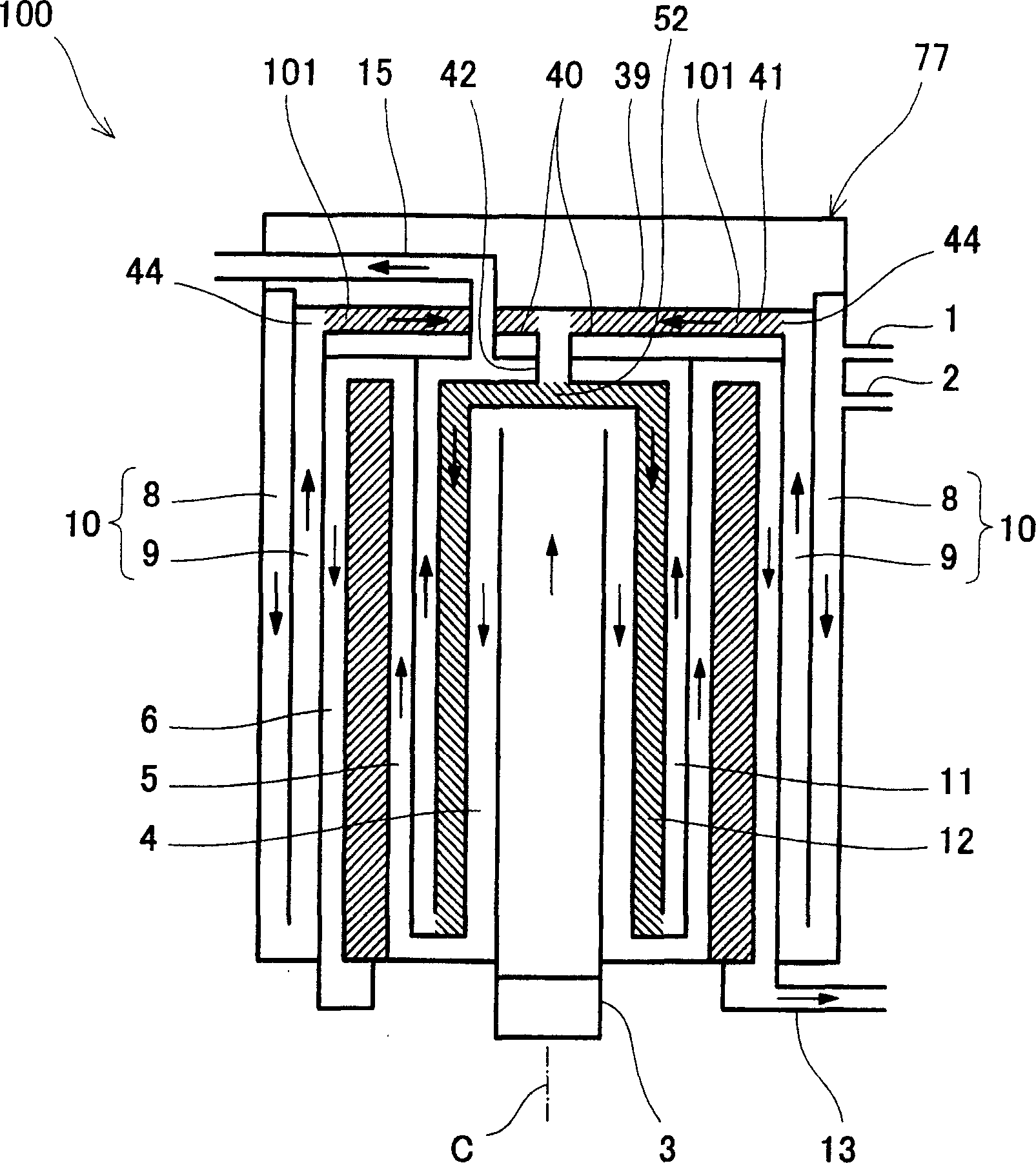
[0149] First refer to figure 1 The basic structure and operation of the hydrogen generator 100 according to Embodiment 1 of the present invention will be described.

[0150] figure 1 It is a longitudinal sectional view schematically showing the internal structure of the hydrogen generator 100 according to Embodiment 1 of the present invention. Also, in figure 1 In , the description of the shif...


PUM


Abstract

The present invention provided a hydrogen generating apparatus having a gas mixer reduced in weight, less in heat capacity, and high in performance and capable of providing excellent hydrogen generating efficiency and responsiveness. This hydrogen generating apparatus comprises a mixed gas flow passage (9) for flowing a mixed gas having two or more components therein, first and second flow passages in which the start ends thereof are branched from the mixed gas flow passage and the terminal ends thereof are converged to each other, first turning means (45a) to (45d) installed in the first flow passage and turning the mixed gas flowing in the first flow passage in a first direction, second turning means (46a) to (46d) installed in the second flow passage and turning the mixed gas flowing in the second flow passage in a second direction opposite to the first direction, and a hydrogen generating part generating hydrogen by chemically acting the mixed gas flowing out of the terminal ends of the first and second flow passages converged to each other.

Description

technical field [0001] The present invention relates to a hydrogen generator that chemically reacts a raw material containing at least an organic compound composed of carbon and hydrogen with water to generate hydrogen, and supplies the hydrogen to a fuel cell. Background technique [0002] Conventionally, a fuel cell combined heat and power system with high power generation efficiency and overall efficiency (hereinafter referred to as a fuel cell system) has been attracting people's attention as a distributed power generation device capable of effectively utilizing energy. [0003] In a fuel cell system, a fuel cell is disposed as the main body of its power generation unit. Most of these fuel cells, such as the practical phosphoric acid fuel cell (PAFC for short) and the solid polymer fuel cell (PEFC for short) currently under development, use hydrogen as the fuel for power generation. However, such a hydrogen supply device is not currently in place as a basic facility. T...

Claims


Application Information

Patent Timeline
Patent Type & Authority Applications(China)
IPC IPC(8): C01B3/38H01M8/06B01F23/10H01M8/0606
CPCY02E60/50
Inventor 向井裕二前西晃田村佳央吉田丰麻生智伦
Owner PANASONIC CORP
Why Eureka
Try Eureka