

Laser processing method and device
A laser processing method and laser processing technology, applied in laser welding equipment, metal processing equipment, optics, etc., can solve the problems of not being able to improve laser utilization efficiency, and achieve the effects of improving utilization efficiency, easy rotation control, and efficient processing
- Summary
- Abstract
- Description
- Claims
- Application Information
AI Technical Summary
Problems solved by technology
Method used
Image

Examples
no. 1 Embodiment approach
[0059] A laser processing apparatus according to a first embodiment of the present invention will be described.
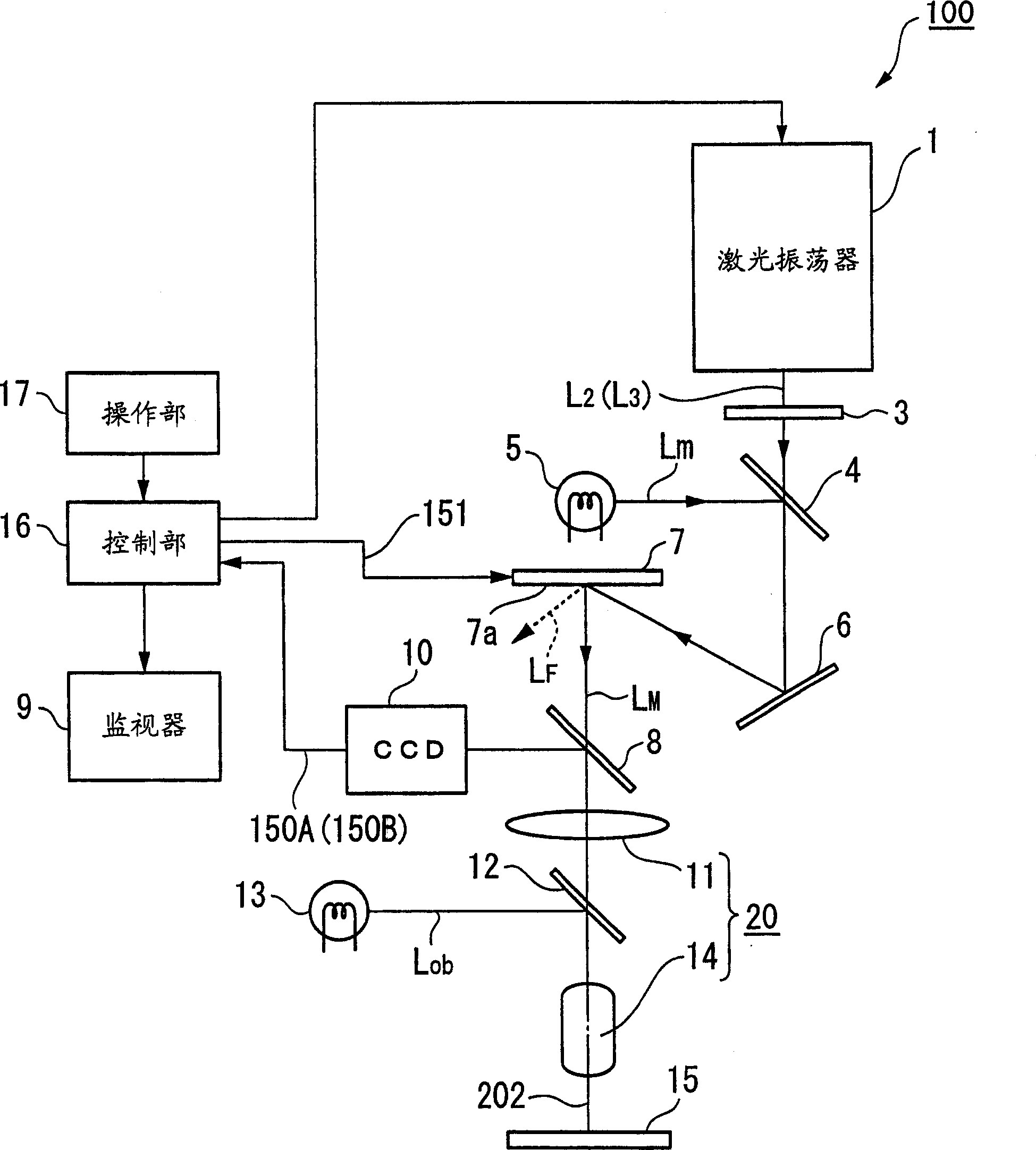
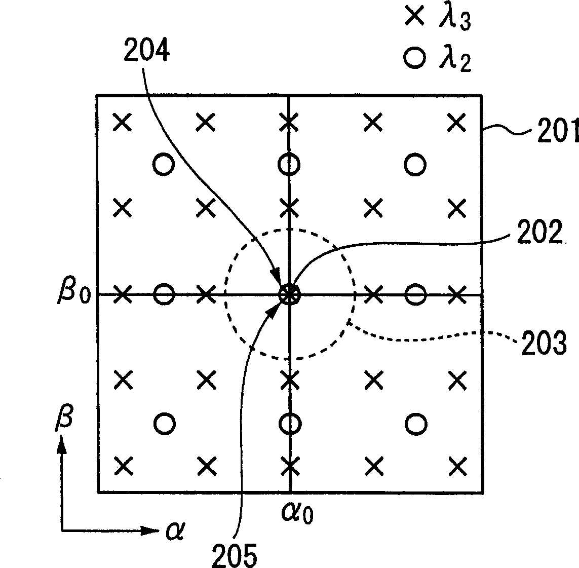
[0060] Such as figure 1 As shown, the laser processing apparatus 100 of this embodiment is an apparatus that divides wavelengths by λ 2 ,λ 3 Laser L 2 , L 3 as modulated light L M Laser processing is performed by irradiating the workpiece 15 .
[0061] Examples of the workpiece 15 include glass substrates, semiconductor substrates, and the like used in liquid crystal displays and the like. In this case, the processing target includes a wiring pattern on a substrate, a defect such as a useless residue existing on a photomask used for exposure, and the like.
[0062] Although not particularly shown, if necessary, the workpiece 15 is held on a mounting table having, for example, a holding mechanism for fixing a position during processing, an adsorption mechanism, and a moving mechanism for moving a processing position. In addition, when used in a microdissecti...
no. 2 Embodiment approach
[0127] A laser processing apparatus according to a second embodiment of the present invention will be described.
[0128] Figure 5 It is a schematic explanatory drawing for demonstrating the schematic structure of the laser processing apparatus 110 which concerns on 2nd Embodiment of this invention.
[0129] Such as Figure 5 As shown, the laser processing apparatus 110 of this embodiment has the laser source 130 instead of the laser oscillator 1 of the laser processing apparatus 100 of 1st Embodiment of this invention. The following description will focus on differences from the first embodiment.
[0130] The laser source 130 oscillates laser light L with different wavelengths in a pulsed manner A , L B (Wavelengths are λ A ,λ B ), a laser source that emits them as approximately parallel beams onto the same optical path. Its schematic structure consists of laser oscillators 1A, 1B, and a dichroic mirror 2 .
[0131] Laser L A , L B The size of the beam diameter can...
no. 3 Embodiment approach
[0152] Next, a laser processing apparatus according to a third embodiment of the present invention will be described.
[0153] FIG. 6 is a schematic explanatory diagram illustrating a schematic configuration of a laser processing apparatus 200 according to a third embodiment of the present invention.
[0154] As shown in FIG. 6, the laser processing apparatus 200 of this embodiment divides the wavelengths by λ according to the processing pattern. 2 , lambda 3 Laser L 2 , L 3 as modulated light L M Laser processing is performed by irradiating the workpiece 15 .
[0155] The laser light L can be used differently according to the wavelength absorption characteristics of the workpiece 15, etc. 2 , L 3 .
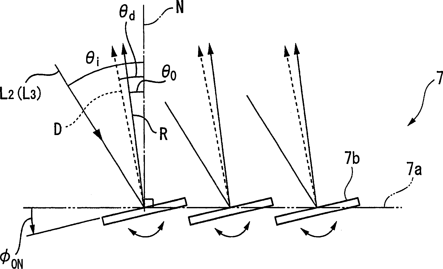
[0156] The general structure of laser processing device 200 is to be made up of following parts: laser oscillator 1 (laser source), tilt table 104 (rotation mechanism), micromirror array 7 (spatial modulator element, active optical element), tilt table 105 (rotation mechan...
PUM
 Abstract
Description
Claims
Application Information