

Hub unit for drive wheel
A technology for driving wheels and hubs, which is applied in the direction of measuring devices, rotating bearings, wheels, etc. It can solve the problems of reduced strength of hinged joints, increased size or weight of hinged joints, etc., and achieves increased strength, simplified shape, and lightweight saving Effect
- Summary
- Abstract
- Description
- Claims
- Application Information
AI Technical Summary
Problems solved by technology
Method used
Image

Examples
no. 1 example
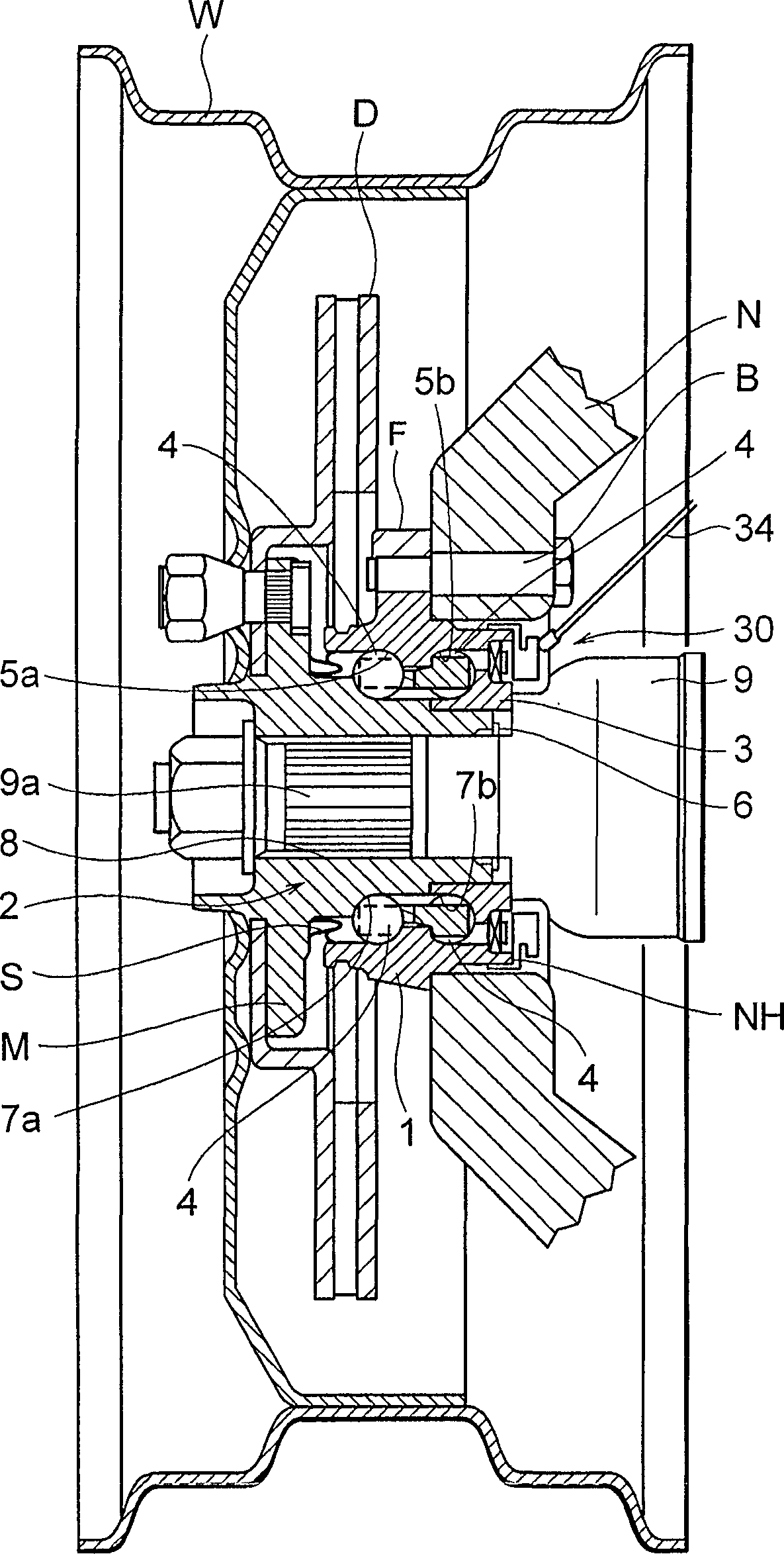
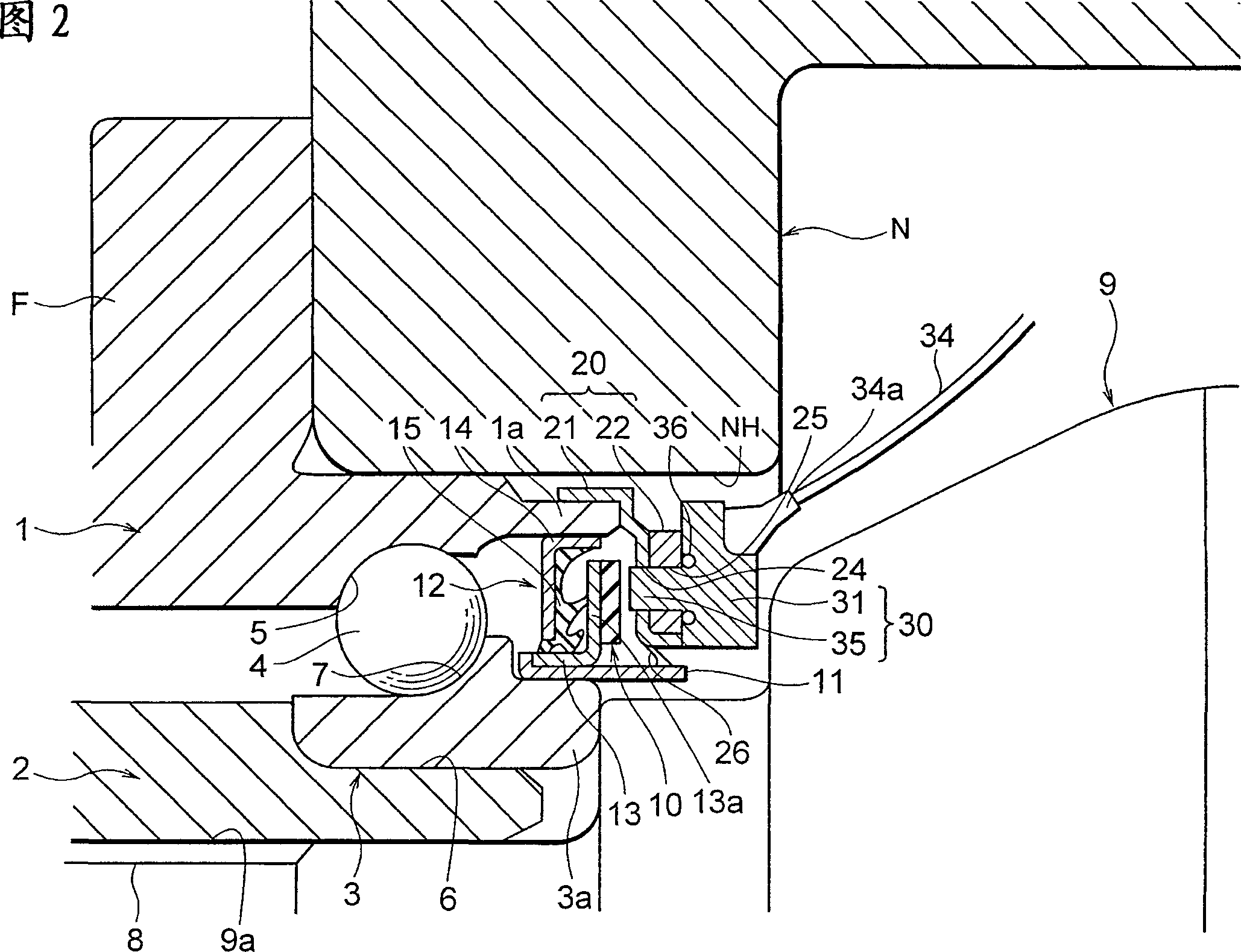
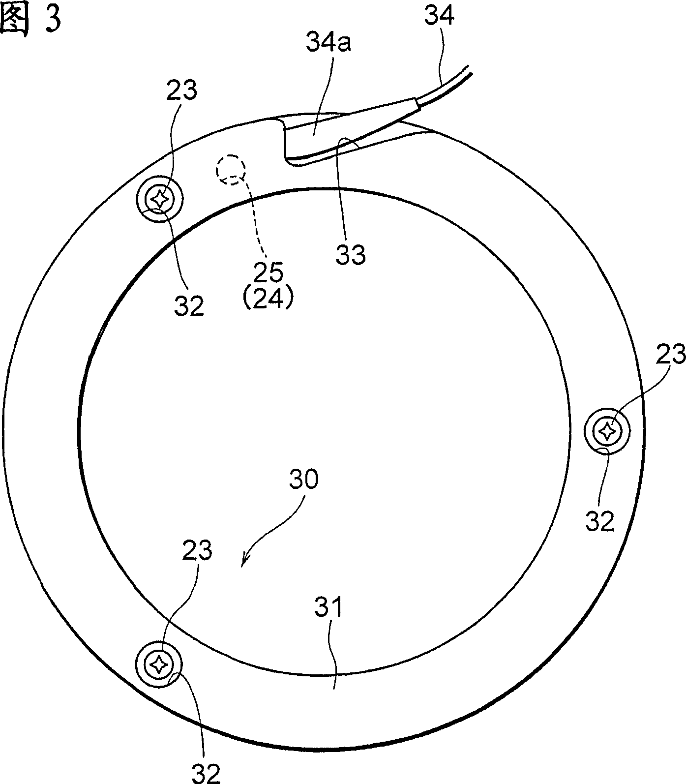
[0112] Fig. 2 is a diagram showing a first embodiment according to the present invention and shown in figure 1 An enlarged cross-sectional view of the main part of the hub assembly for the drive wheel. FIG. 3 is a side view of the sensor for detecting the rotational speed shown in FIG. 2 .
[0113] In the first embodiment, the magnetic encoder 10 is provided on the inner side (the right side in FIG. 2 ) of the inner ring 3 in the vehicle width direction. This magnetic encoder 10 is formed in a disk shape, and is optionally magnetized to have N poles and S poles in its circumferential direction.
[0114] It should be noted that the magnetic encoder may be made of rubber, resin, or the like.
[0115] The magnetic encoder 10 is connected through a seal 12 to a cylindrical member 11 fixed to the inner end portion 3 a of the inner ring 3 in the vehicle width direction.
[0116]The seal 12 includes: a cylindrical core metal piece 13 fixed to the side of the inner ring 3 to the cy...
no. 2 example
[0141] 5 is a schematic diagram showing the internal structure of a sensor for detecting a rotational speed according to a second embodiment of the present invention.
[0142] In the second embodiment, the electronic components a, b, c... of the sensor accommodated in a circumferentially arranged sensor body 31 (cap) are circumferentially arranged along the cap. Furthermore, these electronic components a, b, c... are connected to a wire harness 34 (code or connector).
[0143] As described above, according to the present embodiment, the internal wiring of the sensor 30 for detecting the rotational speed is arranged circumferentially in the sensor main body 31 (cap), which contributes to reducing the size and weight of the hinge joint N and improving its strength. It is also possible to effectively utilize the unused space in the circumferential direction, which contributes to reducing the size of the hub device including the sensor.
[0144] (Modification of the second embodi...
no. 3 example
[0149] 7 is a sectional view of a main part of a hub device for driving wheels according to a third embodiment of the present invention, and FIG. 8 is a perspective view of the hinge joint shown in FIG. 7 .
[0150] The basic structure of the third embodiment is basically the same as that of the aforementioned first embodiment, so only the points of difference will be described.
[0151] The sensor holding member 20 is constituted only of a core metal piece 21 consisting of a cylindrical portion firmly fitted to the inner end portion 1a of the outer ring 1 in the vehicle width direction and a portion having a substantially U-shaped cross section. Composition, the portion having a substantially U-shaped cross-section protrudes inwardly from the inner end of the cylindrical portion in the radial direction so as to surround and hold the sensor main body 31 of the sensor 30 for detecting the rotational speed from the inside in the vehicle width direction.
[0152] The hub device m...
PUM
| Property | Measurement | Unit |
|---|---|---|
| Thickness | aaaaa | aaaaa |
Abstract
Description
Claims
Application Information