Bearing device for wheel

A bearing device, wheel bearing technology, applied in the directions of axles, wheels, bearing components, etc., can solve problems such as no existing technology, and achieve the effects of preventing creep, restraining the reduction of fitting interference, and restraining the change of bearing stiffness

Inactive Publication Date: 2006-12-27
NTN CORP
View PDF0 Cites 6 Cited by
  • Summary
  • Abstract
  • Description
  • Claims
  • Application Information

AI Technical Summary

Problems solved by technology

Since these prior arts are technologies that are actually used and are not dis

Method used


Image

  • Bearing device for wheel
  • Bearing device for wheel
  • Bearing device for wheel

Examples


no. 1 example

[0038] Preferred embodiments of the present invention will be described below with reference to the accompanying drawings.

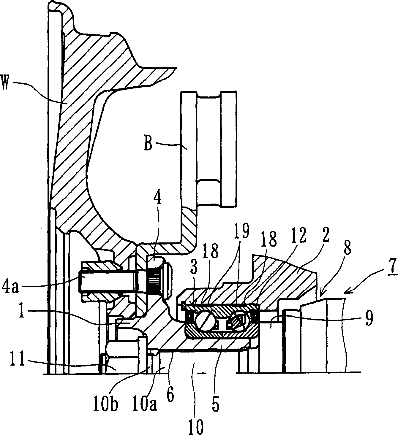
[0039] figure 1 A first embodiment of the bearing device for a wheel of the present invention is shown. In the following description, the term device "outside" means the side that is located outside the vehicle body when the bearing device is mounted on the vehicle body, and the term device "inside" represents a side that is located inside the vehicle body when the bearing device is mounted on the vehicle body. side.

[0040] figure 1The shown bearing device for a wheel of the present invention includes a wheel hub 1 as a main component, and a wheel bearing 3 for rotatably supporting the wheel hub 1 with respect to a steering knuckle 2 . Hub wheel 1 is made of medium carbon steel (eg S53C) containing 0.40-0.80% carbon by weight and includes wheel mounting flange 4 for mounting wheel "W" and brake disc "B" at the outboard end , and a small-diameter ...

no. 2 example

[0050] Figure 4 It is a longitudinal view showing a second embodiment of the bearing device for a wheel of the present invention. This embodiment differs from the first embodiment only in the structure of the outer ring, so the same reference numerals are used to denote the same parts having the same functions as those used in the first embodiment.

[0051] In this wheel bearing 20 , a single annular groove 22 is formed on the outer peripheral surface of an outer ring 21 . The annular groove 22 is formed at the axial center of the outer peripheral surface of the outer ring 21 so that it spans the double row outer raceway surface 12a. The annular groove 22 is filled with a resin band 23 formed by injection molding a heat-resistant thermoplastic synthetic resin based on PA11 (polyamide 11).

[0052] Since the resin band 23 in this second embodiment is formed in the same manner as that of the first embodiment, although the thermal expansion of the knuckle 2 is greater than tha...

no. 3 example

[0054] Figure 5 It is a longitudinal view showing a third embodiment of the bearing device for a wheel of the present invention. This embodiment differs from the first embodiment only in the structure of the wheel bearing, so the same reference numerals are used to denote the same parts having the same functions as those used in the first embodiment.

[0055] In this bearing arrangement for a wheel, a wheel bearing 24 is press-fitted onto the cylindrical portion 5 of the wheel hub 1 and is fixed by being sandwiched between the wheel hub 1 and the shoulder 9 of the outer joint part 8 . The desired bearing preload is obtained by tightening the tightening nut 11 to the threaded portion 10b formed on the end of the shank 10 with a predetermined tightening torque. The wheel bearing 24 is press-fitted into the knuckle 2 formed of light metal such as aluminum alloy with predetermined interference.

[0056] Such as Figure 6 As shown, a wheel bearing 24 has an outer ring 25 , a pa...


PUM


Abstract

To provide a bearing device for a wheel installed on a light-weight light alloy knuckle and capable of preventing preload reduction and bearing creep from occurring due to temperature rise. This bearing device for the wheel comprises a hub wheel (1) integrally having a wheel mounting flange (4) at one end and having a small diameter step part (5) axially extending from the wheel mounting flange (4) formed therein, a wheel bearing (3) formed of a double row bearing disposed in the small diameter step part (5), and the knuckle (2) forming a suspension device and formed of a light alloy. The wheel bearing (3) is press-fitted into the knuckle (2) at a specified interference, and the hub wheel (1) is rotatably pivoted on the knuckle (2). A pair of annular grooves (18) are formed in a loading area on the outer periphery of the outer ring (12) of the wheel bearing (3), and resin bands (19) formed of a heat resistant polyamide synthetic resin and having a coefficient of linear expansion of 8 to 16 x 10<-5>/ DEG C are filled in the annular grooves (18) by injection molding.

Description

technical field [0001] The present invention relates to a bearing device for a wheel, and more particularly relates to the improvement of the installation structure of the wheel bearing. Background technique [0002] Such as Figure 14 As shown, a bearing device 80 for a wheel in the prior art includes: a hub wheel 81 for fixing a brake disc 87 and a wheel (not shown) thereon; an outer ring 82 and a pair of inner rings 83 a wheel bearing 84 for rotatably supporting the hub wheel 81; a steering knuckle 85 for supporting the wheel bearing 84 on the vehicle body; and a constant velocity universal joint 86 adapted to be connected to the hub wheel 81 for For transmitting power from a drive shaft (not shown) to hub wheel 81. [0003] Although ferrous metals such as malleable cast iron having substantially the same linear thermal expansion coefficient as the material forming the hub wheel 81 and the like are used as members forming the bearing device 80, especially the steering kn...

Claims


Application Information

Patent Timeline
IPC IPC(8): F16C25/08F16C33/58B60B35/18
Inventor 小森和雄马场一宏
Owner NTN CORP
Why Eureka
Try Eureka