

Multifunction metal rubber flexible connecting piece
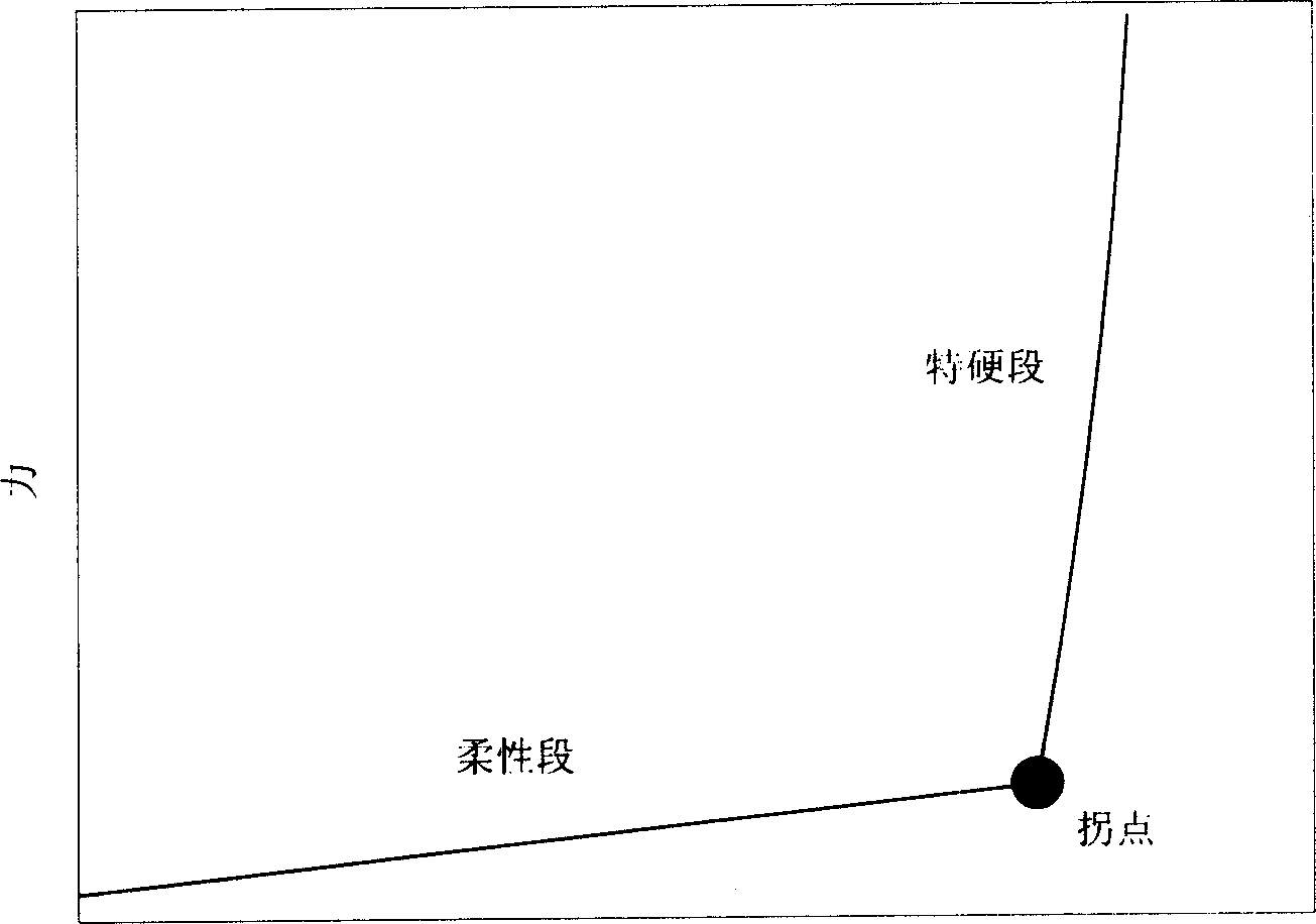
A technology of flexible connectors and metal rubber, applied in the direction of springs, etc., can solve the problems of reducing structural strength, amplifying the low-frequency vibration amplitude of equipment, reducing the reliability of sensitive equipment, and being unable to effectively release thermally induced structural deformation and vibration, etc., to achieve various connection methods , the inflection point of nonlinear stiffness is obvious, and the effect of buffering thermal stress shock
- Summary
- Abstract
- Description
- Claims
- Application Information
AI Technical Summary
Problems solved by technology
Method used
Image

Examples
specific Embodiment approach 1
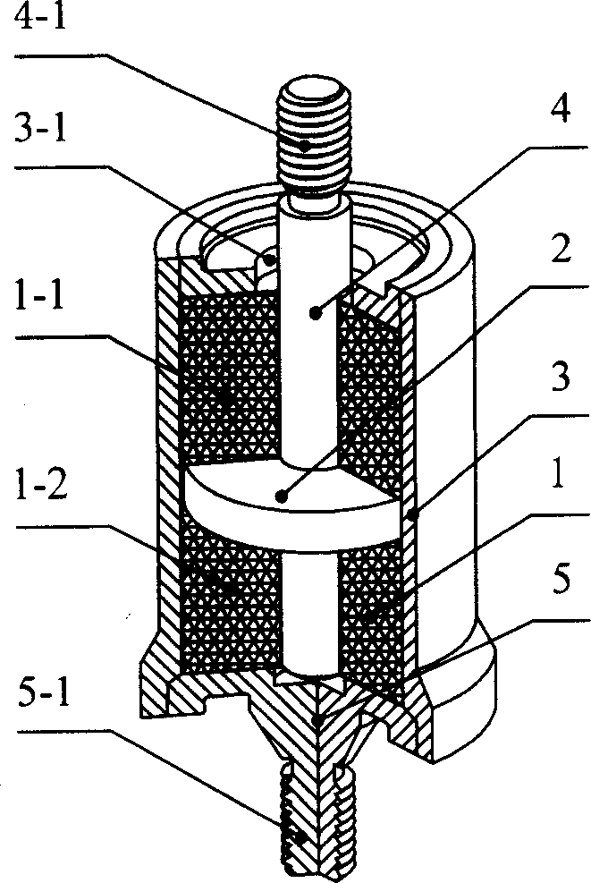
[0007] Specific implementation mode 1: This implementation mode is a multifunctional metal rubber flexible connector, refer to figure 2 , which is composed of a flexible pad 1, a pressure ring 2, a restraint shell 3, a connecting rod 4 and a base 5, the restraint shell 3 is cylindrical, and the flexible pad 1 and the pressure ring 2 are all arranged inside the cylindrical restraint shell 3 , the flexible pad 1 includes an upper flexible pad 1-1 and a lower flexible pad 1-2, the upper flexible pad 1-1 and the lower flexible pad 1-2 are respectively arranged at the upper and lower ends of the pressure ring 2, and the flexible pad 1 is composed of It is prepared from metal rubber. Metal rubber is a grid-like structure formed by winding, superimposing and extruding several spirally coiled metal wires. The upper flexible pad 1-1 and the lower flexible pad 1-2 in this embodiment are selected Metal wires of the same material and diameter are prepared with the same winding density to...
specific Embodiment approach 2
[0012] Specific embodiment two: The end of the constraining shell 3 described in this embodiment is provided with the piercing hole 3-1 of the connecting rod 4, and there is a gap between the connecting rod 4 and the piercing hole 3-1. figure 2 . Since the connecting rod 4 of the connecting piece described in this embodiment does not use a rigid limit in the radial direction, the axes of the connecting joints on both sides of the flexible connecting piece are allowed to form a certain angle, that is, to achieve a certain swing between the base and the equipment, so The nonlinear metal-rubber flexible connector described in this embodiment can simultaneously provide a flexible connection in a bending direction to the base and the device.
specific Embodiment approach 3
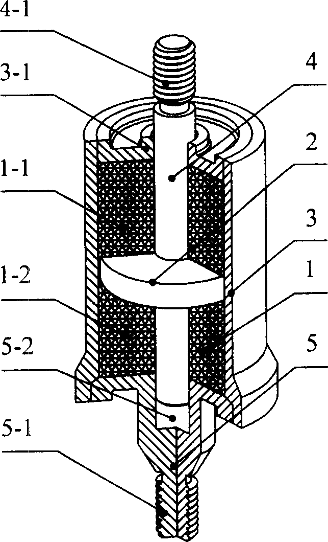
[0013] Specific implementation mode three: combination image 3 This specific embodiment will be described. The difference between this embodiment and the previous embodiment is that a connecting rod guide hole 5-2 is provided on the inner surface of the base 5, and a piercing hole 3-1 of the connecting rod 4 is provided at the end of the constraining shell 3. The inner diameter of the hole 3-1 is the same as the outer diameter of the connecting rod 4, that is to say, there is no gap between the passing hole 3-1 and the connecting rod 4. Since the radial direction of the connecting rod 4 is rigidly limited, only the relative movement of the connecting rod in the axial direction is allowed, thus limiting the swing between the base and the equipment connected at both ends of the flexible connector. Therefore, the connection described in this embodiment The parts can resist shear and bending deformation, and are suitable for connections that require large lateral stiffness, and ...
PUM
 Abstract
Description
Claims
Application Information