
Electrospark machining equipment

A processing equipment and EDM technology, which is applied in the field of EDM equipment, can solve the problems of large processing current, small processing aperture, automatic supply mechanism of filament electrodes, etc., so as to improve processing speed and processing accuracy, prevent longitudinal bending and Effects of vibration and reduction of machining preparation time

Inactive Publication Date: 2007-01-03
MITSUBISHI ELECTRIC CORP
View PDF4 Cites 11 Cited by
  • Summary
  • Abstract
  • Description
  • Claims
  • Application Information

AI Technical Summary

Problems solved by technology

However, in the electrical discharge machining equipment of Patent Document 1, nothing is mentioned about the function of automatically feeding the aforementioned filaments.
In addition, according to the electric discharge machining equipment of Patent Document 1, the electric discharge machining speed of the workpiece can be increased, but it takes time to correct the consumption when using a thin wire electrode, and there is a need for a thin wire electrode in order to shorten the total machining time. The problem of the automatic supply mechanism of the electrode
[0014] In the electrical discharge machining equipment of Patent Document 2, since an elongated, slender and low-rigidity tubular electrode is used, the tubular electrode becomes a spring-like state, and such a tubular electrode is replaced together with the electrode holder. In the case where the electrode replacement mechanism of the patent document 1 is applied to the electric discharge machining equipment of Patent Document 1, there is a problem that the high-response driving performance of the tubular electrode is impaired, and sufficient effects of high-speed and high-precision electric discharge machining cannot be expected.
In addition, the new tubular electrode has a large resistance value due to its long length, but the tubular electrode, which is gradually shortened due to the consumption of EDM, has a gradually reduced resistance value due to EDM.
Therefore, although the electrical conditions during EDM are set to be the same, the machining current will gradually increase during EDM
That is, in the case of hole machining with an electrode-replacing EDM equipment, in the state where the tubular electrode is a new electrode, the diameter of the machining hole is small, and since such a tubular electrode is accompanied by consumption during EDM, the electrode resistance value becomes smaller, so that the machining aperture becomes larger, so there is a problem that the uniform processing quality cannot be guaranteed.
[0015] In the electrical discharge machining equipment of Patent Document 3, the aforementioned thin wire electrodes can be automatically and continuously supplied by rotating and pressing the rollers holding the thin wire electrodes by using the servo motor, however, due to the pressing force of the two rollers on the thin wire electrodes , the filament electrode has the possibility of being deformed into an ellipse, for example. Furthermore, in such a device structure, since the filament electrode cannot be rotated during processing, as mentioned above, the cross-sectional shape of the deformed filament electrode becomes The shape of the hole, so there is a problem that the hole processing with high roundness cannot be performed.
[0016] In the electric discharge machining equipment of Patent Document 4, the conveyance of the filament electrode is carried out by manual operation, and nothing is mentioned about automatic conveyance. Consumable amount of filament electrode, problem that EDM equipment cannot be fully automated
Furthermore, since the wire electrode used in this kind of electric discharge machining equipment has a diameter of φ0.1mm, there is a possibility that the electric discharge machining of the fine hole of the electrode with a small diameter wire whose size is smaller than this value cannot be automatically and continuously performed. The problem

Method used


Image

  • Electrospark machining equipment
  • Electrospark machining equipment
  • Electrospark machining equipment

Examples


Embodiment Construction

[0027] Next, in order to explain the present invention in more detail, the best mode for carrying out the present invention will be described with reference to the accompanying drawings.

[0028] Implementation form 1.

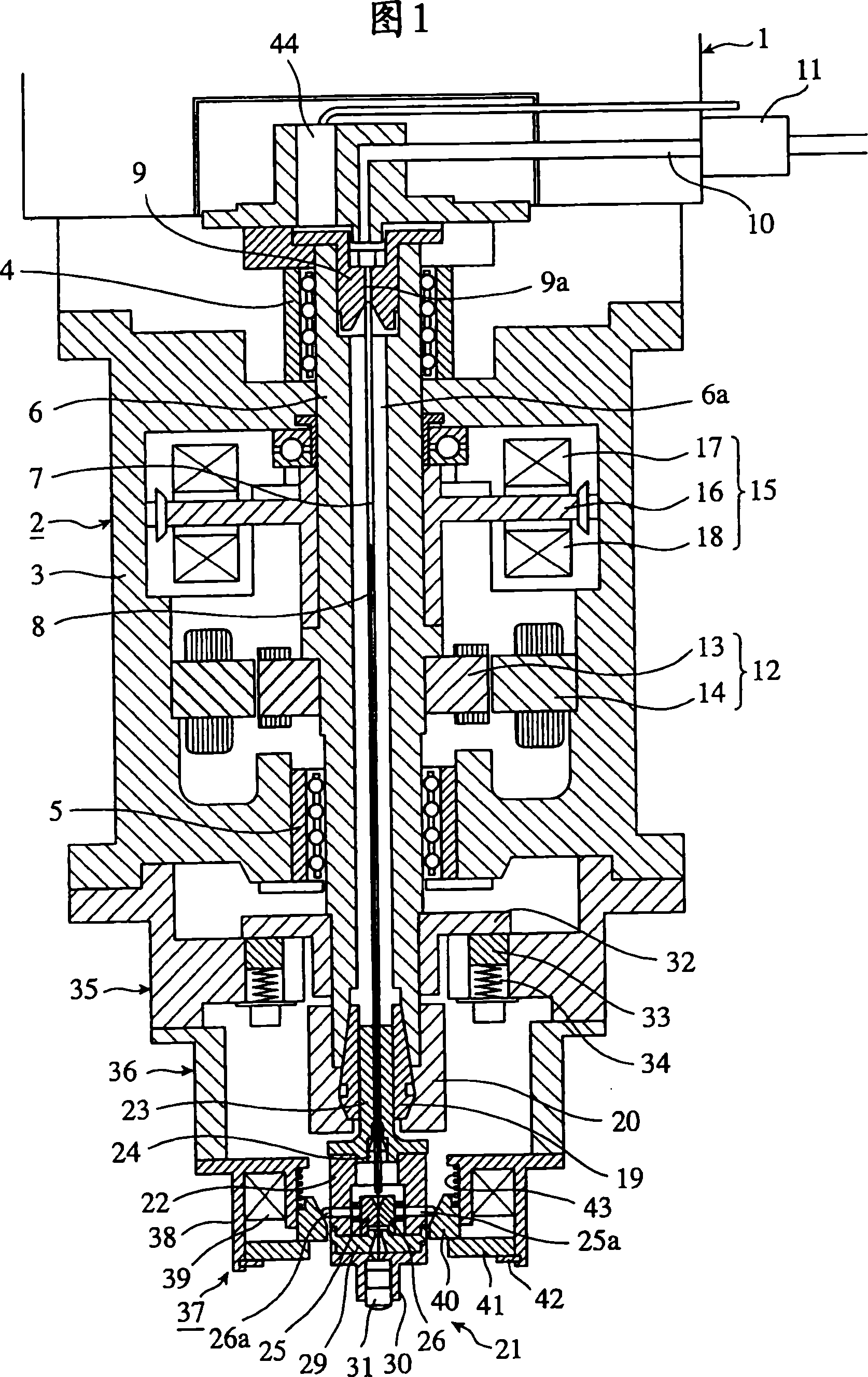
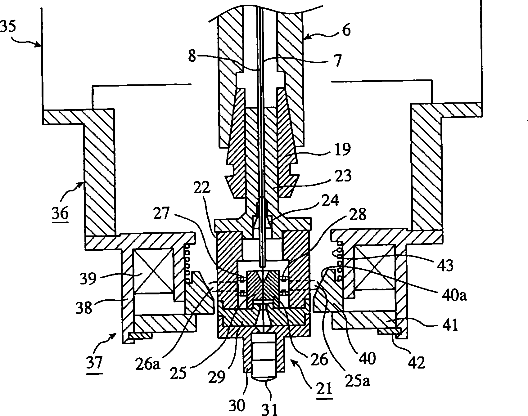
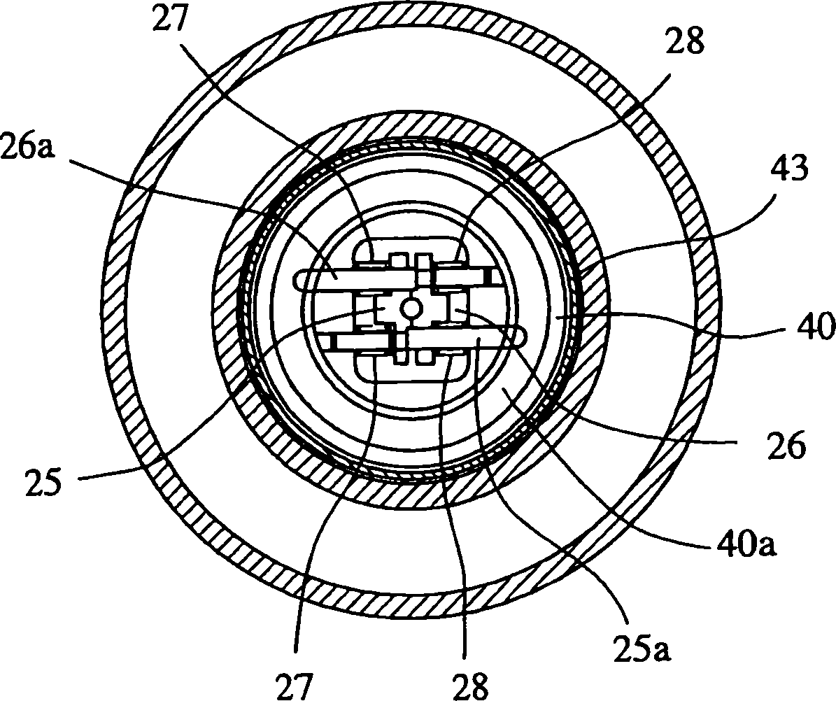
[0029] Fig. 1 shows the electrical discharge machining equipment according to Embodiment 1 of the present invention, figure 2 is an enlarged sectional view of the main part of Fig. 1, image 3 yes figure 2 A cross-sectional view of the main parts.

[0030]In FIG. 1 , a high-speed-response electrode drive device 2 is mounted on a spindle head 1 of an electric discharge machine. This electrode driving device 2 is provided with: a casing 3 which becomes the main body of the device; and a drive shaft 6 which is rotatably mounted on the casing 3 via upper and lower bearings 4, 5 and which can move in the axial direction. inner center. As the bearings 4 and 5, bearings that allow the drive shaft 6 to move in the axial direction (thrust direction), such as a rot...


PUM


Abstract

An electric discharge machine comprising a hollow rod-like guide electrode containing a thin wire electrode for discharge machining slidably, guide electrode grasping means for grasping the guide electrode at a fixed position, pressure fluid supply means for supplying pressure fluid into the guide electrode to feed the thin wire electrode to the discharge machining side from the inside of the guide electrode, and a thin wire electrode grasping means for automatically grasping the thin wire electrode fed out from the guide electrode

Description

technical field [0001] The present invention relates to electric discharge machining equipment for machining holes on workpieces, in particular, relates to electric discharge machining equipment suitable for electric discharge machining microscopic holes on workpieces with filaments as electrodes. Background technique [0002] Generally, such electric discharge machining equipment arranges the machining electrode and the workpiece in the machining fluid, applies a voltage between them to generate electric discharge, and discharges the pores on the workpiece, in order to maintain its stability. According to the processing state, the hole processing of the desired shape is carried out, and a driving device for adjusting the position of the processing electrode or the workpiece is equipped. [0003] The command given to the driving device is controlled by adjusting the position of the processing electrode or the workpiece according to the deviation between the inter-electrode v...

Claims


Application Information

Patent Timeline
Patent Type & Authority Applications(China)
IPC IPC(8): B23H7/30B23H9/14B23H1/10B23H7/26B23H7/36
CPCB23H9/14B23H7/36B23H7/265B23H1/10B23H2400/10
Inventor 三宅英孝中川孝幸今井祥人
Owner MITSUBISHI ELECTRIC CORP
Learn More