2D/3D image display

A display and image technology, applied in image communication, instruments, optics, etc., can solve the problems of high cost, complex production, expensive matrix construction, etc., and achieve the effect of low-cost manufacturing and simplified assembly

Inactive Publication Date: 2007-01-03
KONINKLIJKE PHILIPS ELECTRONICS NV
View PDF3 Cites 31 Cited by
  • Summary
  • Abstract
  • Description
  • Claims
  • Application Information

AI Technical Summary

Problems solved by technology

In many cases, existing monitors are optimized for one of the "normally white" and "normally black" modes, so when operating in the other mode, the contrast ratio will drop, and thus degraded image quality
Furthermore,

Method used


Image

  • 2D/3D image display
  • 2D/3D image display
  • 2D/3D image display

Examples


Embodiment Construction

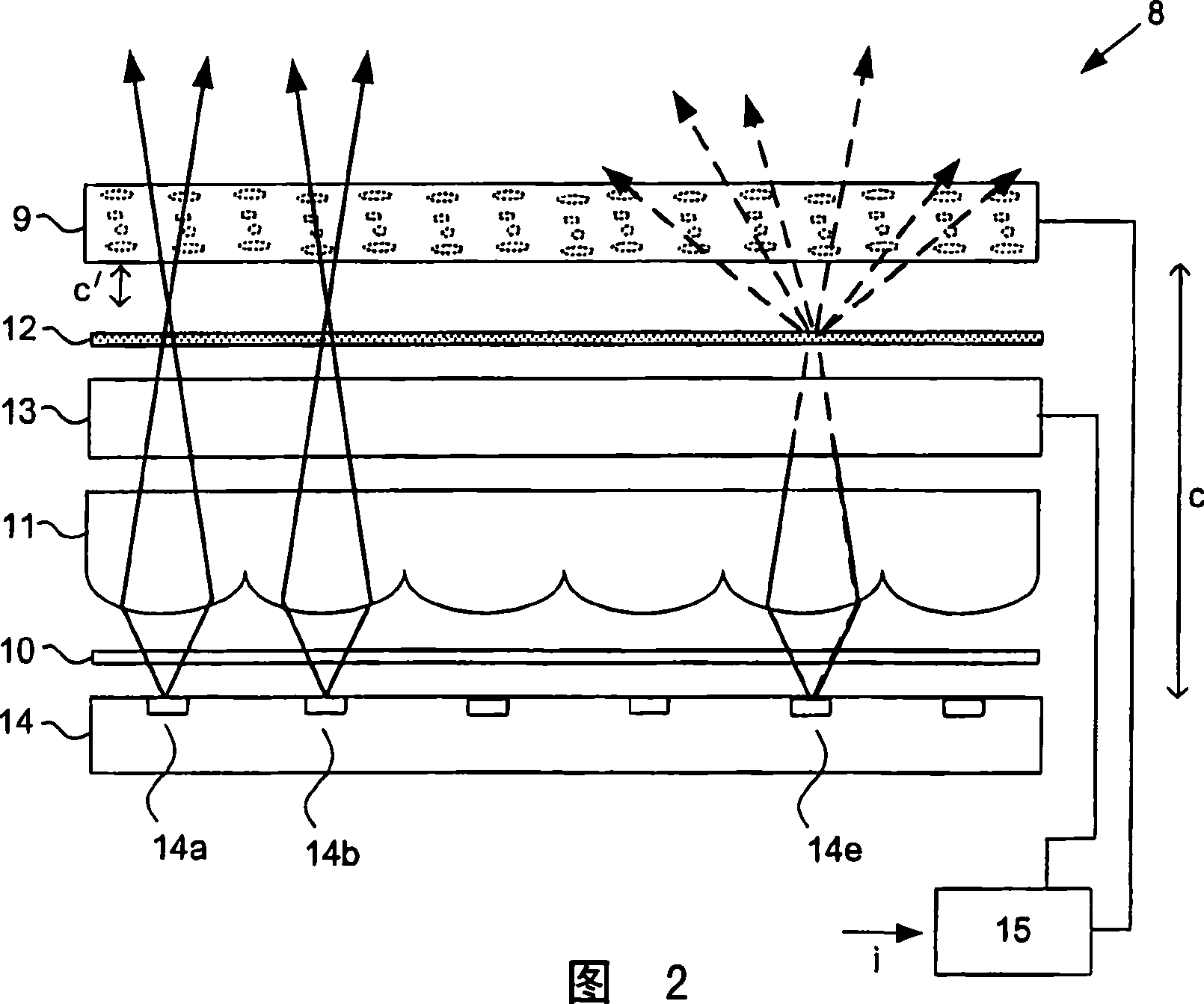
[0047] FIG. 2 depicts a display 8 comprising a display panel 9 in which a two-dimensional array of sub-pixels is defined; a polarizer 10 ; a lenticular screen 11 ; a polarization-dependent diffuser 12 and a switchable polarization rotator 13 . The display 8 also comprises a lighting system 14 configured to generate a backlight for the display panel 9 as described in detail below. In this particular example, each light ray causes a column of four sub-pixels in the display panel 9 to be illuminated. Each sub-pixel in this column can represent a different view, such as views A, B, C, and D, so that by aligning the appropriate pair of frames, a viewer in the appropriate position can perceive the 3D image.

[0048] In this particular embodiment, both the display panel 9 and the polarization rotator 13 comprise a layer of electro-optically active material, such as a liquid crystal material, sandwiched between two light transmissive substrates (not shown). In the case of liquid crys...


PUM


Abstract

A display (8) comprises a display panel (9), a polariser (10), a polarisation rotator (13), and a scatterer (12) arranged to scatter light having a first polarisation as compared with light having a second polarisation. The display (8) can be switched between 2D and 3D modes by operating the polarisation rotator (13) accordingly. In 3D mode, the polarisation rotator (13) transmits light with relatively little or no change to its polarisation. Light transmitted by the scatterer (12) is then used to present a three-dimensional image (50). In 2D mode, the polarisation rotator (13) alters the polarisation of the light and light that is scattered by the scatterer (12) is used to present a two-dimensional image (51). The polarisation rotator (13) maybe arranged so that light incident on a first area thereof undergoes a different change in polarisation to light incident on a second area, in order to allow simultaneous presentation of 2D and 3D images (51, 50).

Description

technical field [0001] The present invention relates to displays capable of presenting two-dimensional and three-dimensional images. Background technique [0002] It is well known that in light valve display devices such as liquid crystal displays (LCDs), the backlight is modulated on a pixel-by-pixel basis by using a liquid crystal matrix. Such devices typically produce two-dimensional (2D) images. However, the research and development of three-dimensional (3D) displays has made rapid progress. For reasons of cost performance and ease of use, display systems have been developed that do not require users to wear special glasses to experience 3D images. These display systems are known as autostereoscopic displays. [0003] Autostereoscopic displays typically comprise a conventional display panel, such as a liquid crystal display (LCD), which, among other devices, provides a pair of images, one image presented to the viewer's left eye and the other image presented to the vi...

Claims


Application Information

Patent Timeline
IPC IPC(8): H04N13/00G02B5/02G02B30/25
CPCH04N13/0456H04N13/0418H04N13/0454G02B5/0278H04N13/0404G02B5/0242H04N13/305H04N13/32H04N13/359H04N13/361G02F1/1333G02F1/1335
Inventor W·L·利泽尔曼H·J·科内利森
Owner KONINKLIJKE PHILIPS ELECTRONICS NV
Why Eureka
Try Eureka