Sewing machine

A sewing machine and housing technology, applied in sewing machine components, sewing equipment, program-controlled sewing machines, etc., can solve problems such as time-consuming, and achieve the effect of reducing setting time and avoiding adjustment.

A sewing machine and housing technology, applied in sewing machine components, sewing equipment, program-controlled sewing machines, etc., can solve problems such as time-consuming, and achieve the effect of reducing setting time and avoiding adjustment.

CN1891887AInactive Publication Date: 2007-01-10DURKOPP ADLER AG

Image

  • Sewing machine
  • Sewing machine
  • Sewing machine

Examples


Embodiment Construction

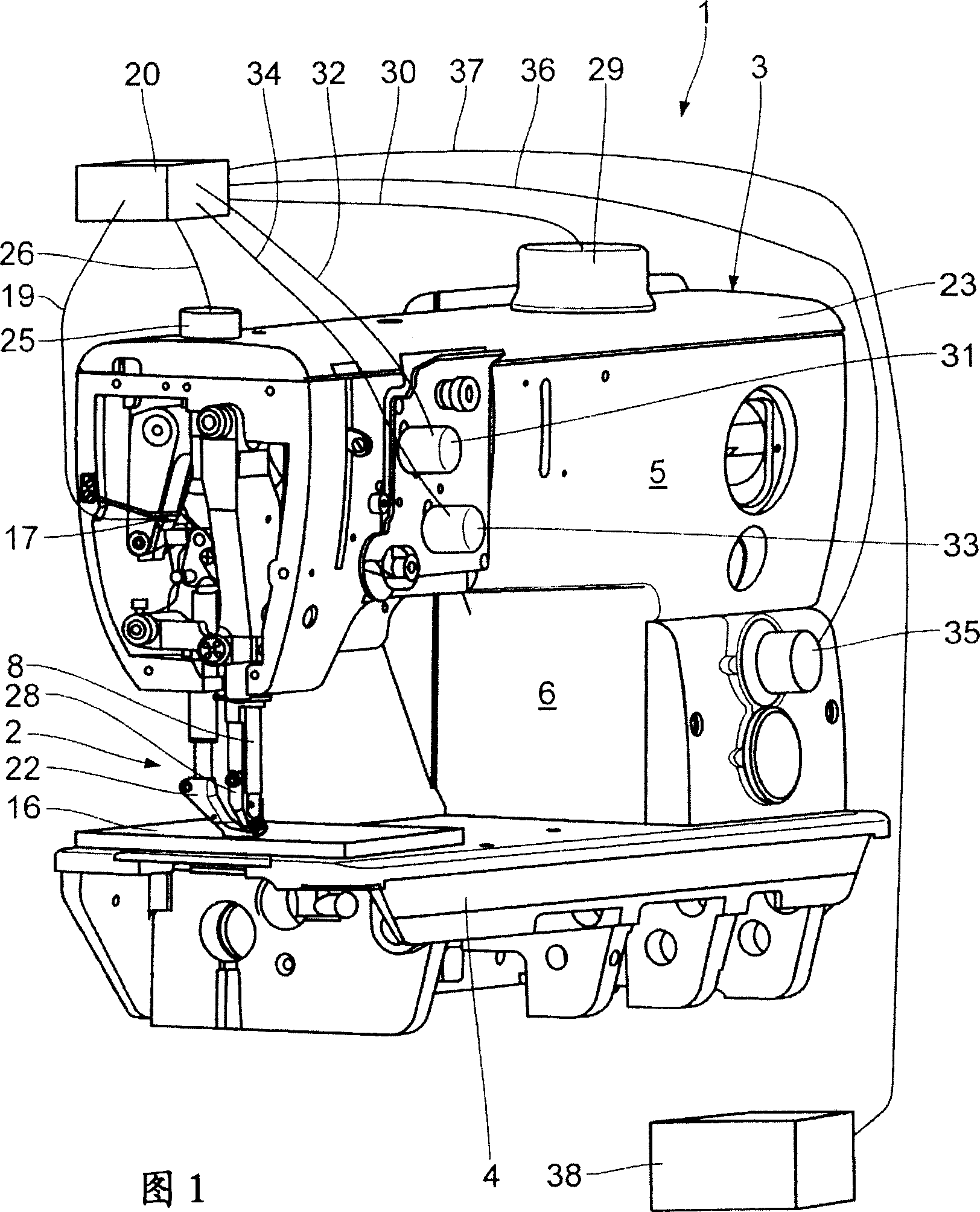
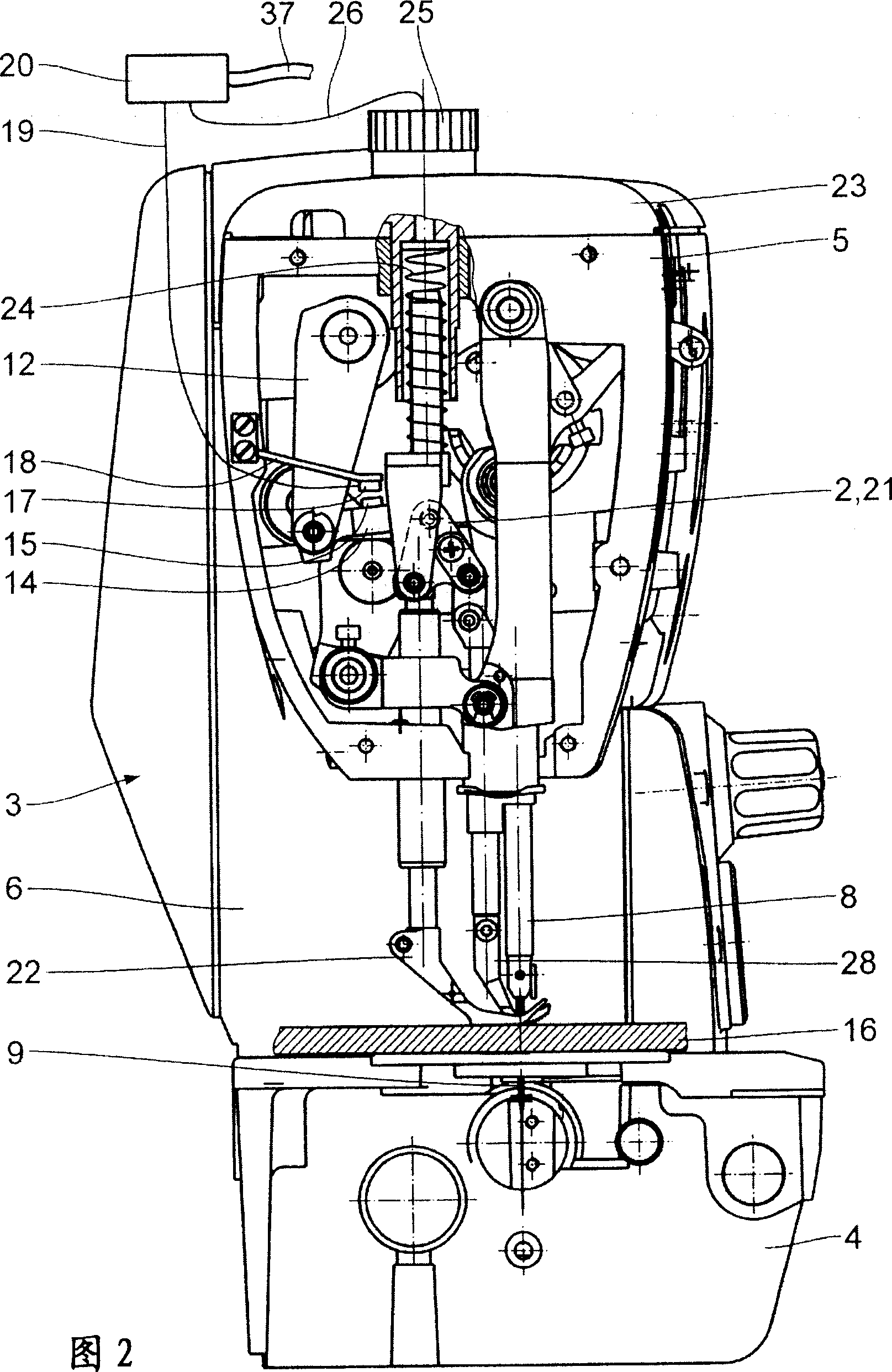
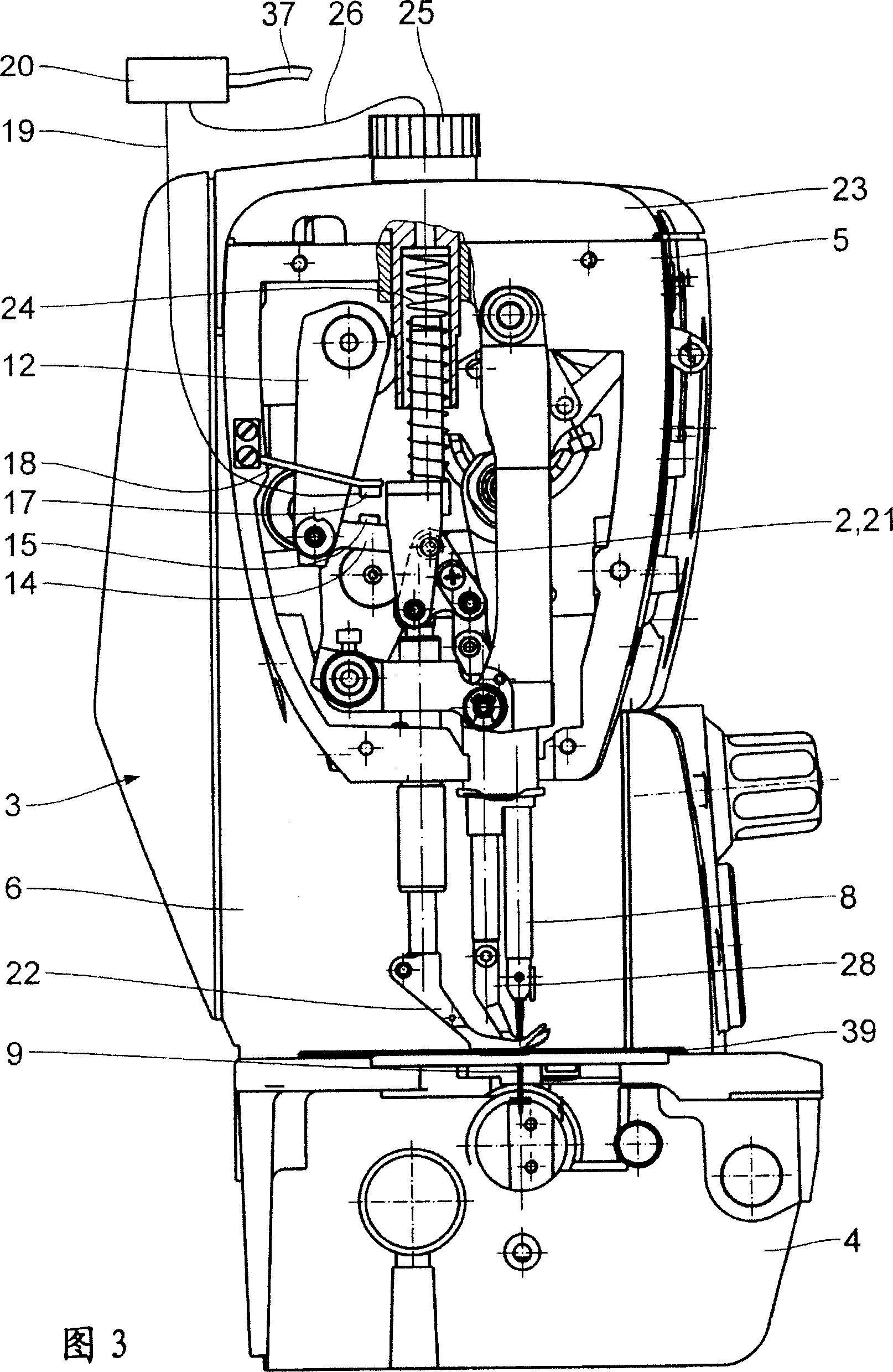
[0020] Figures 1-3 realistically show a partially disassembled sewing machine 1 except for the control components. Figure 4 and 5 A schematic diagram of the sewing machine 1 is shown showing the coupling of the mechanical parts of the top feed device generally referenced 2 . The basic design of the sewing machine 1 is quite common, so only the components which are important for the invention will be described below.

[0021] The sewing machine 1 has a C-shaped housing 3 . The housing 3 includes a base plate 4 and a top arm 5 . To form the C-shape, the uprights 6 join the base plate 4 and the arms 5 . The arm 5 houses an arm shaft 7 driven by a motor (not shown) (see Figure 4 ). The needle bar 8 with the sewing needle 9 is moved up and down and the top feeder 2 is moved by a rotational mechanical coupling with the arm shaft 7 . Regarding the actuation of the top feeder 2, see in Figure 4 and 5 The kinematic design of the device 2 is clearly shown, the arm shaft 7 being ...


PUM


Abstract

The invention provided a sewing machine, improved to automatically switch the sewing machine to the thickness of cloth. This sewing machine includes: a housing having a base plate; a top arm; and a strut for integrating the base plate with the top arm. A metallic presser presses a cloth piece near a stitch forming position. The metallic presser driven by a movable rod is capable of moving between the lift position for releasing the cloth piece and the pressing position for the cloth piece to be pressed. When the metallic presser moves between these positions, the distance of at least one movable rod part from a reference structure fixed to the housing stably changes. The position sensor detects the position of the metallic presser in the pressing position. A control system makes signal connection thereto. The system sets an adjustment variable for the sewing machine depending upon the output value of the position sensor. As a result, the obtained sewing machine automatically performs switching to the thickness of variable cloth piece.

Description

technical field [0001] The invention relates to a sewing machine, which comprises: a shell; a base plate; a top arm; a column connecting the base plate and the top arm; at least one lower pressing plate used to press the fabric, and the lower pressing plate can pass through a movable rod The assembly moves between an elevated state in which the fabric is released and a depressed state in which the fabric is pressed; the movable rod assembly has at least one movable rod portion, and the distance between the movable rod portion and a reference structure fixed to the housing is There is a continuous change between the raised state and the depressed state. Background technique [0002] A common type of sewing machine is known, for example, from DE 3043141 A1. Once there is some variation in the thickness of the fabric to be sewn with this type of sewing machine, it is necessary to manually readjust the sewing machine or modify the program of the sewing machine, which is time-co...

Claims


Application Information

Patent Timeline
10 Jan 2007
Publication
CN1891887A
IPC
D05B21/00; D05B27/00; D05B29/00
CPC
D05B19/12; D05B27/04; D05B29/00
Inventors
C·黑克纳; H·塞贝特