Industrial waste-gas purifier

A purification device and industrial waste gas technology, which is applied in the direction of combined devices, chemical instruments and methods, and dispersed particle filtration, can solve the problems of complex structure and high processing cost of industrial waste gas purification devices, and achieve convenient maintenance and management, low operating costs, and improved The effect of the purification effect

A purification device and industrial waste gas technology, which is applied in the direction of combined devices, chemical instruments and methods, and dispersed particle filtration, can solve the problems of complex structure and high processing cost of industrial waste gas purification devices, and achieve convenient maintenance and management, low operating costs, and improved The effect of the purification effect

CN1895736AInactive Publication Date: 2007-01-17白金龙

Image

  • Industrial waste-gas purifier
  • Industrial waste-gas purifier
  • Industrial waste-gas purifier

Examples


Embodiment Construction

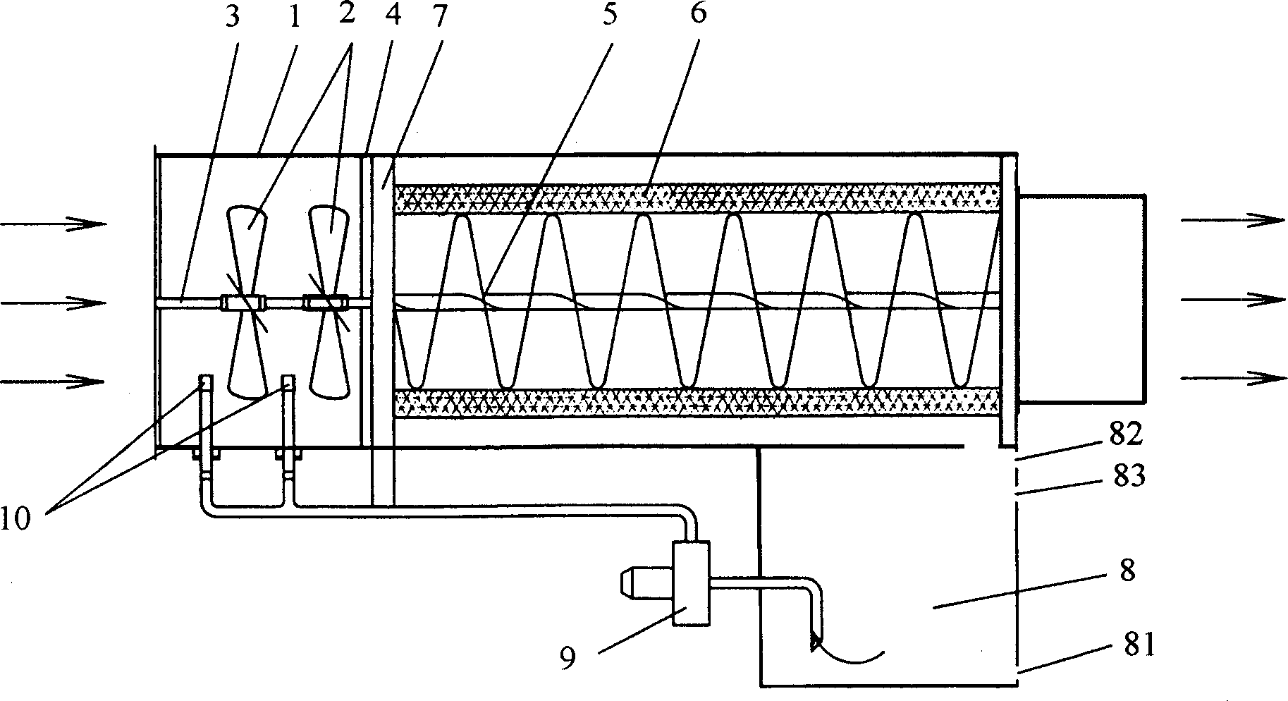
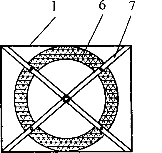
[0020] see figure 1 with 2 , the present invention is provided with hollow rectangular housing 1, 2 impellers 2, rotating shaft 3 and fixed support 4, spiral deflector 5, cylindrical filter 6 and fixed support 7, water tank 8, water pump 9 and 2 spray liquids Head 10. The impeller 2 is arranged on the rotating shaft 3 at the front part of the inner chamber of the housing 1 , and the two ends of the rotating shaft 3 are arranged on the two ends of the inner chamber of the housing 1 and fixed on the fixed bracket 4 . The spiral deflector 5 is arranged at the center of the housing behind the impeller 2 , and the cylindrical filter 6 is sleeved outside the spiral deflector 5 . Water.8 is located below the rear of the housing 1, the water inlet on the top of the water tank 8 is connected to the water outlet of the housing 1, the water tank 8 is provided with a sewage outlet 81, and the liquid spray head 10 is arranged on the impeller 2 of the inner cavity of the housing 1 Below ...


PUM


Abstract

An industrial waste gas cleaning apparatus with simple structure is composed of casing, at least one blade wheel, rotary shaft, spiral flow guider, cylindrical filter and its supporter, water tank with water inlet and blow-off outlet, water pump and at least one liquid sprayer.

Description

technical field [0001] The invention relates to a gas separation device, in particular to a purification device mainly used for industrial waste gas. Background technique [0002] Industrial waste gas is a major source of pollution. Various toxic gases (such as sulfur dioxide and hydrogen sulfide, etc.) and particulate inhalants contained in industrial waste gas cause serious air pollution to the public environment. Existing treatment technologies include mechanical separation, wet treatment, electrostatic treatment, adsorption filtration, biological treatment and low-temperature plasma treatment. [0003] The utility model patent with the notification number CN2355778 provides a biological industrial waste gas purification device. The lower part of the housing is provided with an aeration pipe and a water inlet pipe, and the upper part is provided with a water outlet pipe. The carrier network located in the upper part of the aeration pipe and the water inlet pipe It is com...

Claims


Application Information

Patent Timeline
17 Jan 2007
Publication
CN1895736A
IPC
B01D50/00; B01D53/78
CPC
B01D47/06; B01D47/18; B01D46/24; B01D50/008; B01D50/10
Inventors
白金龙