Vortex compressor and its vacuum preventer

A scroll compressor and vacuum technology, applied in the direction of rotary piston machinery, rotary piston pumps, components of pumping devices for elastic fluids, etc., can solve the problem of reducing compressor compression efficiency, inconvenience, and lubricating oil residue and other issues to achieve the effect of improving production efficiency, reducing costs, and easy processing

Inactive Publication Date: 2007-01-17
LG ELECTRONICS (TIANJIN) APPLIANCES CO LTD
View PDF0 Cites 9 Cited by
  • Summary
  • Abstract
  • Description
  • Claims
  • Application Information

AI Technical Summary

Problems solved by technology

[0012] 2. Moreover, the piston hole 122 is formed laterally on the side wall of the fixed scroll 106, so the machining of the piston hole is complicated and difficult, and it is difficult to process the piston hole 122 with precise dimensions, so the gap between the piston 124 and the piston 124 becomes smaller. Large, leaks the pressure of the high-pressure chamber, and reduces the compression efficiency of the compressor
[0013] 3. A pressure-receiving chamber 122a is formed at the inner front end of the piston hole 122, and a part of the refrigerant in the compression chamber 112 flows into the above-mentioned pressure-receiving chamber 122a through the guide passage 121 as a guide pressure and makes the piston 124 work, but flows from the compression chamber 112 into the pressurized The guiding refrigerant in the chamber 122a contains lubricating oil, so the above-mentioned lubricating oil remains in the pressure receiving chamber 122a and affects the normal operation of the piston 124.
[0014] This shows that the above-mentioned existing scroll compressor vacuum prevention device obviously still has inconvenience and defects in structure and use, and needs to be further improved urgently
In order to solve the problems existing in the vacuum prevention device of the scroll compressor, the relevant manufacturers have tried their best to find a solution, but no suitable design has been developed for a long time, and there is no suitable structure for general products. To solve the above problems, this is obviously a problem that the relevant industry is eager to solve

Method used


Image

  • Vortex compressor and its vacuum preventer
  • Vortex compressor and its vacuum preventer
  • Vortex compressor and its vacuum preventer

Examples


Embodiment Construction

[0060] In order to further explain the technical means and effects of the present invention to achieve the intended purpose of the invention, the specific implementation and structure of the vacuum prevention device for scroll compressors proposed according to the present invention will be described below in conjunction with the accompanying drawings and preferred embodiments. , features and their effects are described in detail below.

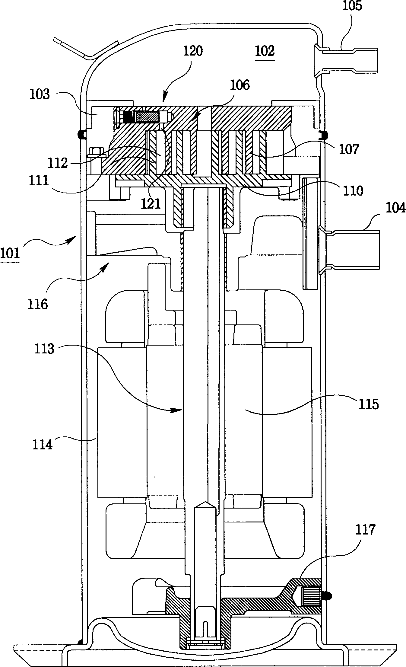
[0061] see Figure 4 Shown is a longitudinal sectional view of a scroll compressor using the first embodiment of the vacuum preventing device of the present invention. The scroll compressor of the present invention includes: a cylindrical casing 1 divided into a low-pressure chamber 2 having a suction pipe 3 for sucking in refrigerant from the outside and a high-pressure chamber 4 having a discharge pipe 5 for discharging high-pressure refrigerant; Equipped with an involute-shaped compression chamber 23, the low-pressure refrigerant in the ab...


PUM


Abstract

This invention is a kind of scroll type compressor and its vacuum preventing device. The vacuum preventing device includes element splitting the inside of casing into high-pressure chamber and low-pressure chamber. It is arranged above the fixing scroll; inner passage linking the said element and high and low pressure chambers; piston hole cross forming on the said inner passage; piston arranging at the said piston hole. It opens the said inner passage only when the pressure of compressing chamber is lower than certain pressure; the first passage linking the said high-pressure chamber and the said piston hole; the second passage in order to make the said pistons not meet; connecting part forming at different positions of the said second passage and piston holes. It links the front end of the said piston hole and second passage.

Description

technical field [0001] The present invention relates to a kind of scroll compressor, especially relate to a kind of when the working fluid can't flow into the compression chamber due to the circulation obstacle when the scroll compressor is working, it communicates the high pressure chamber and the low pressure chamber of the compressor and prevents compression. A scroll compressor whose chamber works in a vacuum state and its vacuum prevention device. Background technique [0002] In a typical scroll compressor, an orbiting scroll rotated by a crankshaft has an involute orbiting leg, and forms an involute compression chamber with an involute fixed leg of a fixed scroll. The orbiting scroll moves eccentrically through the rotation of the crankshaft and gradually reduces the volume of the compression chamber to compress the fluid in the compression chamber. When a certain compression ratio is reached, the compressed fluid is discharged through the exhaust port. [0003] The ...

Claims


Application Information

Patent Timeline
Patent Type & Authority Applications(China)
IPC IPC(8): F04C18/02F04C29/00
Inventor 周永世
Owner LG ELECTRONICS (TIANJIN) APPLIANCES CO LTD
Why Eureka
Try Eureka