Permanent magnetism synchrounous electromotor control device

A permanent magnet synchronous control device technology, applied in the direction of motor generator control, AC motor control, electronic commutation motor control, etc., can solve the problems of torque characteristic deterioration, permanent magnet synchronous motor influence, and no record of synchronous operation load fluctuation Countermeasures and other problems to achieve the effect of suppressing speed fluctuations

Inactive Publication Date: 2007-01-17
HITACHI APPLIANCES INC
View PDF2 Cites 5 Cited by
  • Summary
  • Abstract
  • Description
  • Claims
  • Application Information

AI Technical Summary

Problems solved by technology

[0006] In the conventional method of correcting the induced voltage constant for synchronous operation, countermeasures are provided for the decrease in the stability of the permanent magnet synchronous motor caused by the deviation of the induced voltage constant of the permanent magnet synchronous motor, but there is no description of the method for synchronous operation. Countermeasures against load fluctuations
[0007] In addition, in the conventional V / f constant control, the fluctuation part of the detected value of the q-axis current is fed back to the frequency command value to improve the stability against the load fluctuation, but it is easy to Due to the influence of the coil resistance of the permanent magnet synchronous motor, the torque (torque) characteristic deteriorates
[0008] In this way, although the driving method based on synchronous operation at low speeds has excellent torque characteristics and is suitable for starting permanent magnet synchronous motors, it is necessary to take countermeasures against load fluctuations.

Method used


Image

  • Permanent magnetism synchrounous electromotor control device
  • Permanent magnetism synchrounous electromotor control device
  • Permanent magnetism synchrounous electromotor control device

Examples


Embodiment 1

[0035] Embodiment 1 of the related permanent magnet synchronous motor of the present invention will be described.

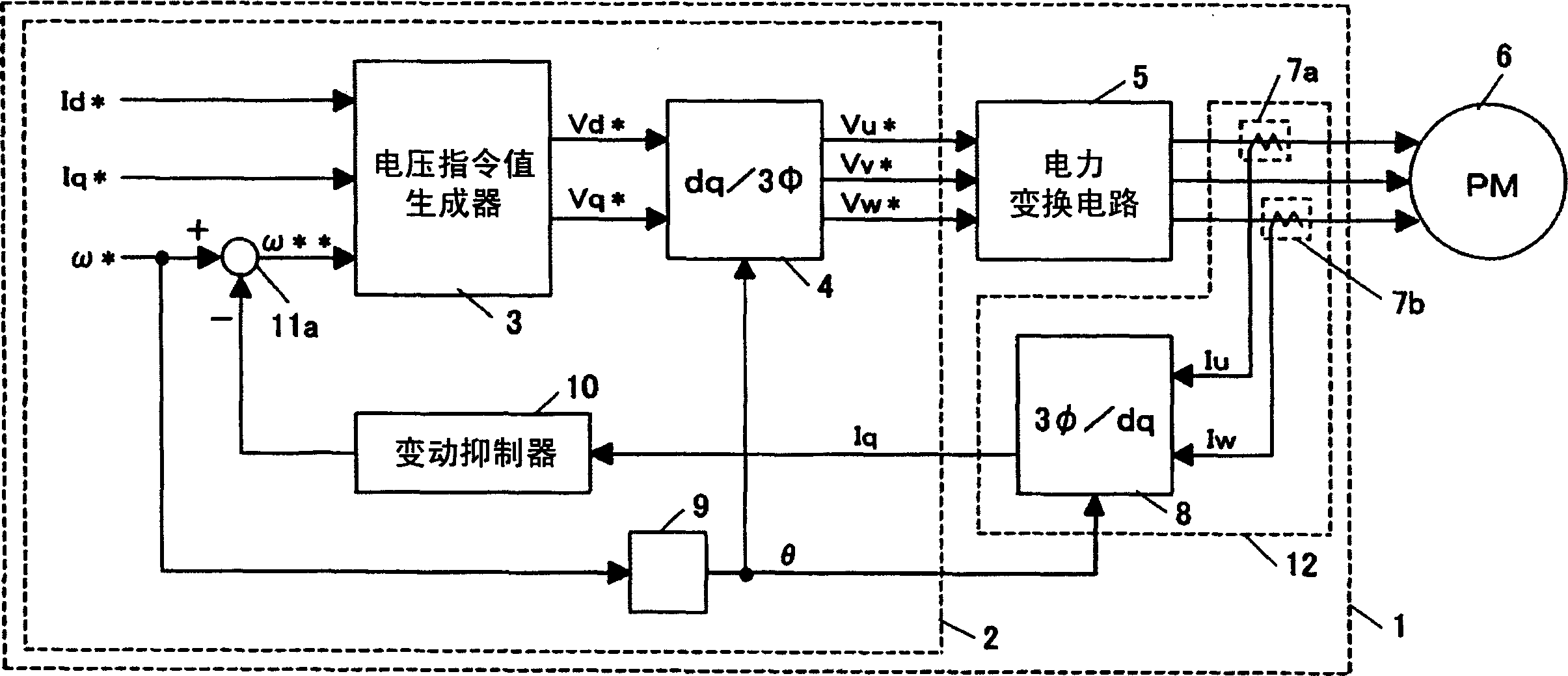
[0036] First compare figure 1 , the current detection means 12 for obtaining the q-axis current flowing in the permanent magnet synchronous motor will be described.

[0037] The current detection means 12 is composed of a detection means for detecting the three-phase alternating current, and a means for converting the three-phase axes into dq axes and obtaining the d-axis and q-axis currents. As detection means for detecting 3-phase alternating current, current detecting circuits (7a and 7b) are used in the present invention to detect U-phase and W-phase in the 3-phase alternating current flowing through the permanent magnet synchronous motor.

[0038] Since the permanent magnet synchronous motor 6 is Y-connected, it is only necessary to detect two or more phases of the alternating current flowing through the permanent magnet synchronous motor. In addition, any...

Embodiment 2

[0068] control Figure 5 ~ Figure 8 Embodiment 2 of the related permanent magnet synchronous motor of the present invention will be described.

[0069] The current detection mechanism 12a that detects the d-axis and q-axis currents flowing in the permanent magnet synchronous motor, and inputs the current detected by the current detection mechanism 12a and outputs the 3-phase voltage command value that is finally applied to the permanent magnet synchronous motor 6 (Vu * 、Vv * 、Vw * ) is different from Embodiment 1 in the configuration of the control unit 2a. In this embodiment, using the detection values ​​of the d-axis and q-axis currents, the three-phase voltage command values ​​(Vu * 、Vv * 、Vw * ).

[0070] First, the current detection mechanism 12a that detects the d-axis and q-axis currents flowing through the motor will be described.

[0071] Such as Figure 6 As shown, the current detection mechanism 12a is composed of the current detection circuit 7c and the cu...

Embodiment 3

[0102] control Figure 9 Embodiment 3 of the control device for the related permanent magnet synchronous motor of the present invention will be described.

[0103] Figure 9 It is a schematic diagram illustrating the washing machine 200 when the control device 201 for the permanent magnet synchronous motor of the present invention is applied to the drive system of the washing machine.

[0104] The washing machine 200 is provided with a washing tank 206 and an agitating blade (vibrator) 205 in a water tank 208 , and the washing tank 206 and the agitating blade 205 are driven by a motor 203 . Which one of the washing tub 206 and the stirring blade 205 is driven is switched by the clutch unit 204 in the washing step.

[0105] In addition, the clutch unit 204 may also be provided with a reduction mechanism. The control device 201 of the permanent magnet synchronous motor applies an AC voltage to the permanent magnet synchronous motor 203 through the wiring 202 for driving.

[...


PUM


Abstract

The present invention provided a controller which effectively controls the velocity when starting a permanent magnet synchronous motor in synchronous operation mode. The controller for a permanent magnet synchronous motor, which is equipped with a permanent magnet synchronous motor that has a permanent magnet as a field, a voltage command maker which gets a voltage command to be applied to the above permanent magnet motor, according to a d-axis current command, a q-axis current command, and a frequency command, and a power converting circuit which applies voltage to the above permanent magnet synchronous motor, according to the above voltage command, detects the q-axis current of the permanent magnet synchronous motor when starting the above permanent magnet synchronous motor in synchronous operation mode, and applies gain to the detected q-axis current value, and subtracts the operation results from the above frequency command thereby modifying the frequency command.

Description

technical field [0001] The present invention relates to a control device for a permanent magnet synchronous motor that stably drives a permanent magnet synchronous motor, particularly a control device for a permanent magnet synchronous motor suitable for stabilization when the permanent magnet synchronous motor is started in a synchronous operation mode. Background technique [0002] As a method for stably starting a permanent magnet synchronous motor, there is, for example, a control device for a permanent magnet synchronous motor described in Japanese Unexamined Patent Publication No. 2004-104978 (Patent Document 1). [0003] In the prior art of the aforementioned Patent Document 1, a d-axis current command value, a frequency command value, and a real q-axis current are input, vector calculation is performed, and switching signals for each element of the inverter are generated. [0004] The induced voltage constant of the permanent magnet synchronous motor is used in the v...

Claims


Application Information

Patent Timeline
Patent Type & Authority Applications(China)
IPC IPC(8): H02P27/06H02P6/16H02P6/18H02P21/00H02P21/22H02P21/34H02P27/08
Inventor 铃木尚礼户张和明金子大吾远藤常博山崎明
Owner HITACHI APPLIANCES INC
Why Eureka
Try Eureka