
Integrated circuit, method for controlling differential signal and communication system

An integrated circuit, differential technology, applied in transmission systems, baseband systems, digital transmission systems, etc., can solve problems such as expensive, reduced forward communication bandwidth, and limited transmission speed.

Inactive Publication Date: 2010-05-12
RAMBUS INC
View PDF4 Cites 2 Cited by
  • Summary
  • Abstract
  • Description
  • Claims
  • Application Information

AI Technical Summary

Problems solved by technology

Adding leads and signal paths is expensive and undesirable
As an alternative, bi-directional communication can support reverse channel signaling, but this option may reduce the bandwidth of forward communication
[0006] In a paper titled "Phantom Mode Signaling in VLSI Systems," Thaddeus Gabara describes how the common-mode signals to achieve reverse-channel communication in high-speed differential channels. These circuits take advantage of the ability of modern differential receivers to reject common-mode signals; Inserting a common-mode signal is no different than inserting common-mode noise. Therefore, a reverse-channel communication scheme that relies on common-mode signaling techniques will undesirably limit the transmission speed of the forward channel. Therefore, there is a need for a reverse channel that can be achieved through a high-speed differential channel Protocols and circuits for channel communication without unduly limiting differential signal bandwidth.

Method used


Image

  • Integrated circuit, method for controlling differential signal and communication system
  • Integrated circuit, method for controlling differential signal and communication system
  • Integrated circuit, method for controlling differential signal and communication system

Examples


Embodiment Construction

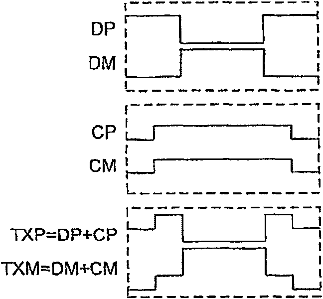
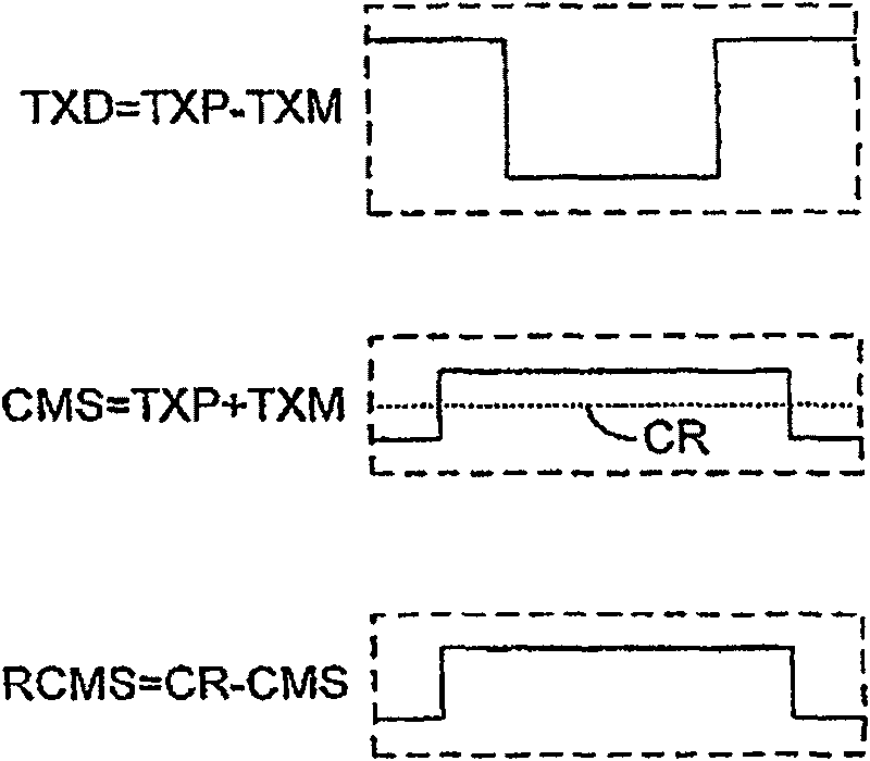
[0060] figure 1 A communication system 100 is shown according to one embodiment. As with conventional systems, the system 100 includes a differential transmitter 105 connected to a corresponding differential receiver 107 via a differential communication channel 109 . System 100 also includes reverse channel communication circuitry, common mode transmitter 127 transmits a reverse channel signal synchronized to clock signal TCK to common mode receiver 129 via channel 109 . The high speed differential link between transmitter 105 and receiver 107 is called the "forward channel", while the relatively slower common mode link between transmitter 127 and receiver 129 is called the "reverse channel".

[0061] Various parameters of the differential transmitter 105 should be tuned to achieve and maintain optimum performance. Such tuning affects, for example, on-die termination resistance, drive current, signal swing, equalization (in the transmitter), and phase offset. In addition, f...


PUM


Abstract

Described are communication systems that convey differential and common-mode signals over the same differential channel. Noise-tolerant communication schemes use low-amplitude common-mode signals thatare easily rejected by differential receivers, thus allowing for very high differential data rates. Some embodiments employ the common-mode signals to transmit backchannel signals for adjusting the characteristics of the differential transmitter. Backchannel control signals are effectively conveyed even if the forward channel transmitter is so maladjusted that the received differential data is unrecognizable. Systems in accordance with the above-described embodiments obtain these advantages without additional pins or communications channels, and are compatible with both AC-coupled and DC-coupled communications channels. Data coding schemes and corresponding data recovery circuits eliminate the need for complex, high-speed CDR circuits.

Description

technical field [0001] User demands for digital video, high-speed communications, and ever-increasing processing speeds are driving manufacturers to adopt faster data transfer solutions. Although the data transmitted is usually digital, designers are keen on analog communication schemes that use low-voltage differential signaling, especially for moving data within a system. The transmission medium or "channel" can be a pair of copper wires, but is more commonly a pair of circuit board traces running between integrated circuits. The use of differential signals allows common mode noise to be suppressed and thus enables data transmission to be particularly fast and immune to common mode noise. Background technique [0002] The Telecommunications Industry Association (TIA) publishes standards that specify the electrical characteristics of Low Voltage Differential Signaling (LVDS) interface circuits that can be used to interchange binary signals. LVDS uses low-voltage different...

Claims


Application Information

Patent Timeline
Patent Type & Authority Patents(China)
IPC IPC(8): H03K19/003H04L12/56G06F13/40H04L5/20
CPCH04L25/0276H04L47/10H04L5/20H04L25/02H03K19/003
Inventor 安德鲁·霍弗拉迪米尔·斯托杰诺维克弗雷德·F·陈伊拉德·阿朗马克·A·霍罗威茨
Owner RAMBUS INC
Learn More