Evaporator device

A technology for evaporators and distributors, which is applied in the field of vapor deposition devices, can solve the problems of not providing linear distributor orifices, etc., and achieve the effects of low energy loss, improved thermal isolation, and uniform symmetry

Inactive Publication Date: 2007-01-31
APPL THIN FILMS INC
View PDF9 Cites 6 Cited by
  • Summary
  • Abstract
  • Description
  • Claims
  • Application Information

AI Technical Summary

Problems solved by technology

Also no linear distributor orifice is provided in this coating device

Method used


Image

  • Evaporator device
  • Evaporator device
  • Evaporator device

Examples


Embodiment Construction

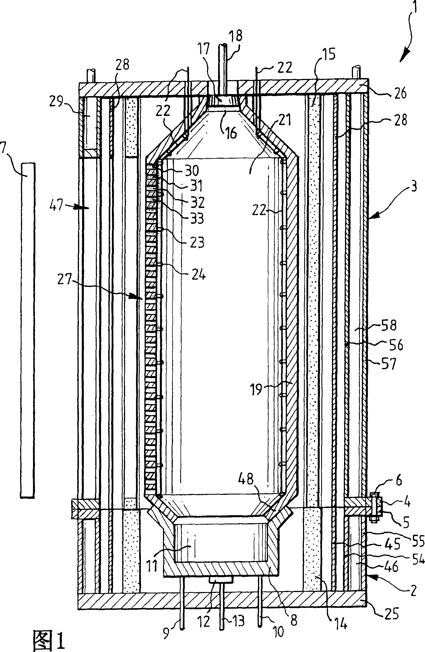
[0017] FIG. 1 shows a longitudinal sectional view of an evaporator device 1 consisting of a lower housing part 2 and an upper housing part 3 . The upper housing part 3 is here placed on the lower housing part 2 . The lower shell part 2 and the upper shell part 3 are fixed together by means of connecting clamps 4 , 5 and connecting pins 6 . When the lower housing part 2 is placed on the base 25 , the upper housing part 3 is closed by the cover 26 . As an alternative to the connecting lugs 4, 5, a simple plug connection can also be provided.

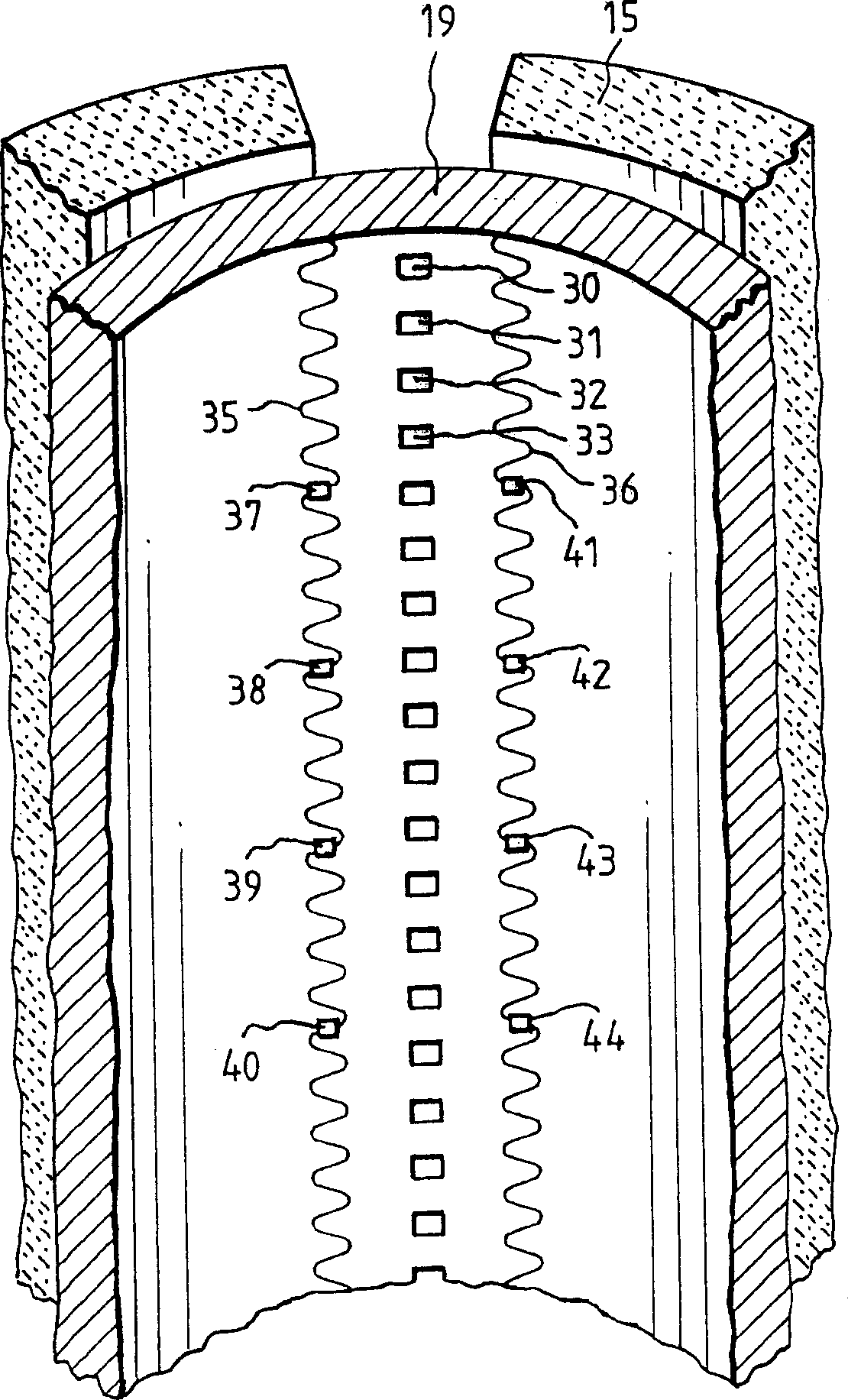
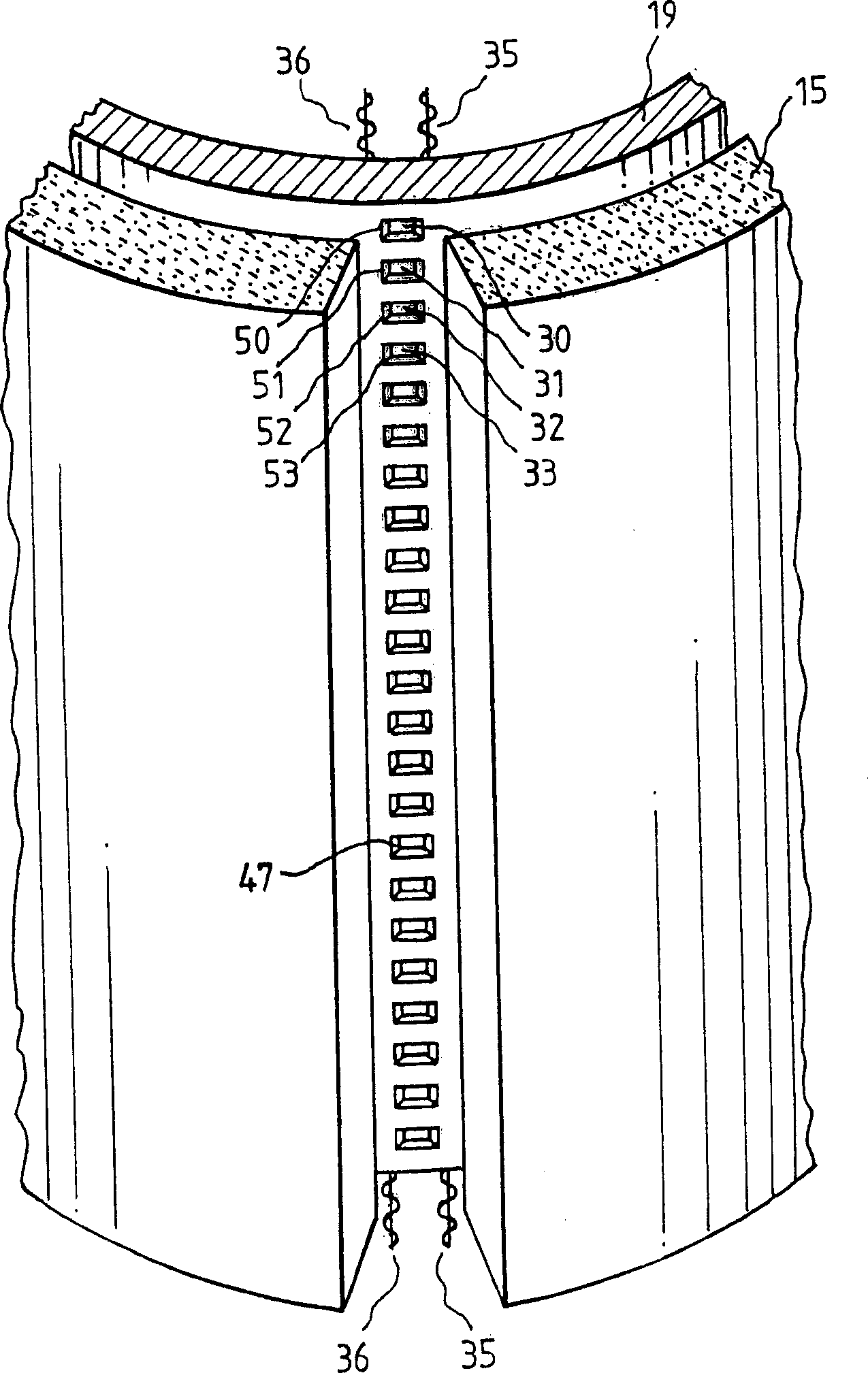
[0018] Inside the upper shell part 3 is provided an evaporator tube 19 comprising a number of nozzles 30, 31, 32, 33 arranged linearly one below the other through which steam can flow from the evaporator tube. escape. This vapor is deposited on the surface of the substrate 7 which can be moved through the evaporator device 1 into the plane of the drawing.

[0019] The crucible 8 is arranged below the evaporator tube 19 which rests on t...


PUM


Abstract

The present invention relates to an evaporator device for coating substrates, in particular for applying an aluminum layer of OLEDs. In order to attain high evaporator tube temperatures, such as are required for example for the vaporization of materials with low vapor pressure, the heating system is placed into the interior of the evaporator tube. The thermal losses are thereby minimized and higher tube temperatures are possible at comparably couple in heating power.

Description

[technical field [0001] The present invention relates to a vapor deposition apparatus, and more particularly, the present invention relates to a vapor deposition apparatus having an evaporator source for vapor deposition of a substrate. Background technique [0002] Modern flat panel displays include liquid crystal elements (LCE) or plasma elements for displaying images or characters. [0003] Recently, flat panel displays have also been produced using organic light emitting diodes (OLEDs) as color pixels. [0004] A great advantage of OLEDs compared to known structural elements is their high efficiency of more than 16% (Helmuth Lemme: OLEDs-Senkrechtstarter aus Kunststoff, Elektronik 2 / 2002, p.98, right column, 2nd paragraph, No.[ 5]: Yi He; Janicky, J.: High Efficiency Organic Polymer Light-Emitting Heterostructure Devices, Eurodisplay 99, VDE-Verlag Berlin, Offenbach). Furthermore, the efficiency of OLEDs is much higher than the quantum efficiency of LEDs composed of in...

Claims


Application Information

Patent Timeline
Patent Type & Authority Applications(China)
IPC IPC(8): C23C14/24C23C14/26C23C14/14
CPCC23C14/243C23C14/26C23C14/14H10K71/164H10K10/486
Inventor M·本德尔U·霍夫曼G·科勒姆D·哈斯U·英格勒特
Owner APPL THIN FILMS INC
Why Eureka
Try Eureka