Sputtering device and sputtering method

A sputtering device and assembly technology, which is applied in the direction of sputtering plating, ion implantation plating, metal material coating process, etc., can solve the problems of uneven film quality, non-promoting reaction, etc., and achieve the effect of uniform film quality

Active Publication Date: 2007-01-31
ULVAC INC
View PDF1 Cites 4 Cited by
  • Summary
  • Abstract
  • Description
  • Claims
  • Application Information

AI Technical Summary

Problems solved by technology

In this case, if reactive gas is introduced into the sputtering device to perform reactive sputtering, the reaction is not pr

Method used


Image

  • Sputtering device and sputtering method
  • Sputtering device and sputtering method
  • Sputtering device and sputtering method

Examples


Embodiment 1

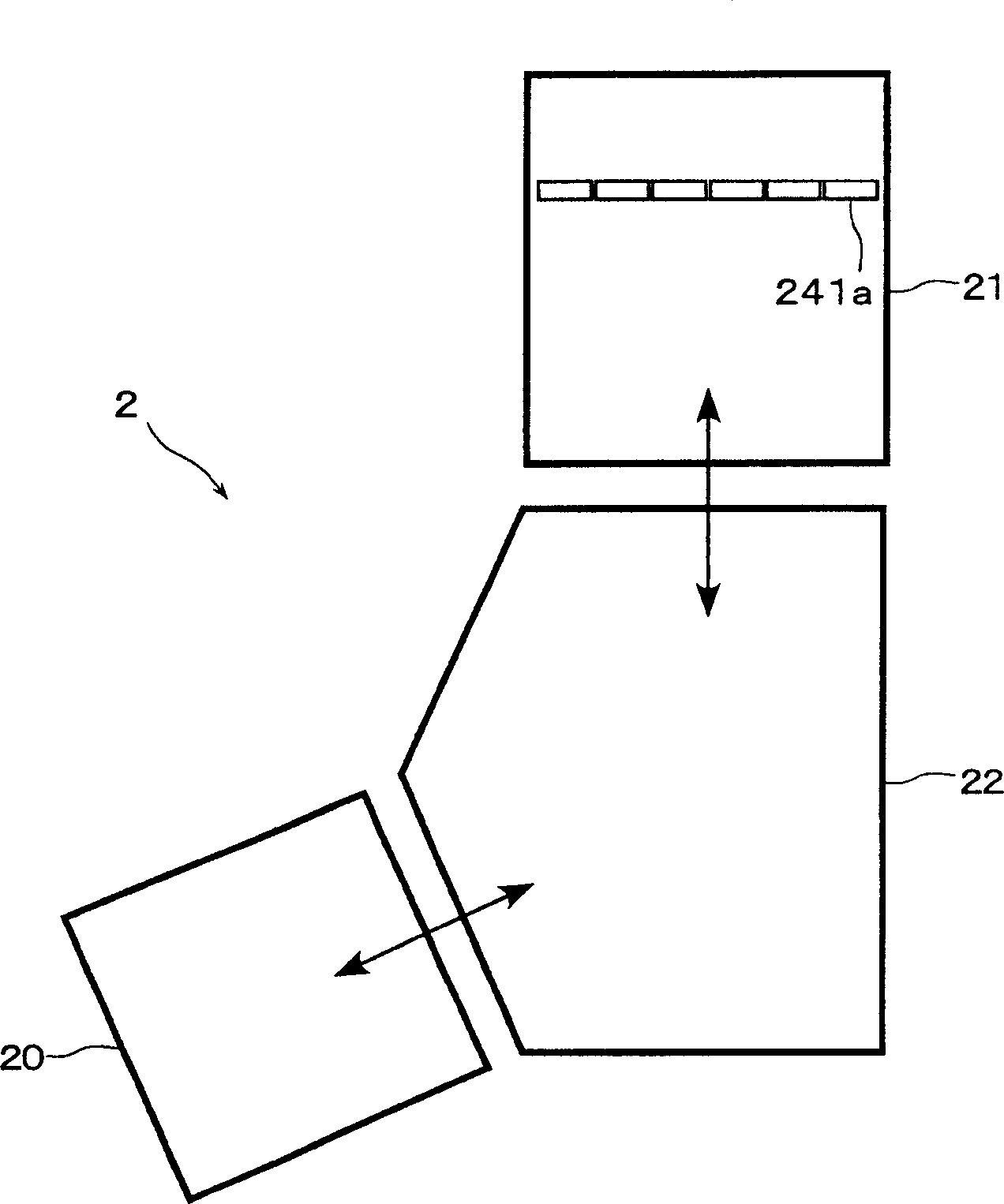
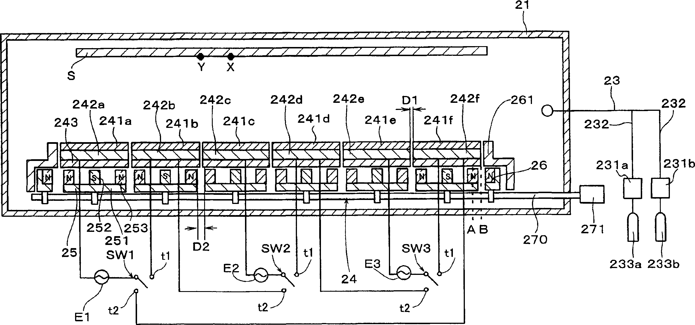
[0064] In Example 1, using figure 2 and image 3 Films were formed using the sputtering device shown in , and the number of occurrences of arc discharge during film formation was studied.

[0065] Will be composed of In 2 o 3 -10wt%SnO 2 A target made of (ITO) was installed parallel to the substrate at a position 150 mm away from the substrate. The target width was 2 mm, respectively. A magnet assembly with a width of 170 mm, a length of 1570 mm, and a thickness of 40 mm was installed behind each target so that the distance from each target was 47 mm, and the ball screw 271 was used to make the driving distance 50 mm. As a substrate, a glass substrate having a width of 1000 mm, a length of 1200 mm, and a thickness of 0.7 mm was prepared.

[0066] After the substrate was transported, evacuation was performed, and then argon gas was introduced from the gas introduction unit 23 at 240 sccm as a sputtering gas to form a film-forming atmosphere of 0.67 Pa. Additionally, H w...

Embodiment 2

[0071] In Example 2, using figure 2 and image 3 In the sputtering apparatus shown in , the in-plane uniformity of film quality was evaluated when reactive sputtering was performed.

[0072] The flow rate of the reaction gas during film formation was changed, and the flow rate at which the resistivity decreased the most at each point on the film was investigated, and the in-plane uniformity of film quality was evaluated using the difference in the flow rate.

[0073] Using the same sputtering apparatus as used in Example 1, a plurality of films were formed by changing the flow rate of the reaction gas in Example 1. As a reactive gas, H 2 The flow rate of O gas was set at 2.0 sccm, and O was introduced so that the flow rate was changed from 0.0 sccm to 4.0 sccm in increments of 0.2 sccm. 2 gas. The frequency of each AC power supply E was 25 kHz, and the power was gradually increased from 0 kW to 15 kW at last. The AC power supply was stopped 25 seconds after the AC power s...


PUM

PropertyMeasurementUnit
Thicknessaaaaaaaaaa

Abstract

A sputtering apparatus which does not spoil the non-corrosive area on the target and gives uniform film during the reactive sputtering process is disclosed. The sputtering apparatus 2 comprises:(a) supplying a space to set more than three targets 241 in the vacuum chamber 21. (b)using alternating current power supply E1~E3 to alternatively charge each target 241 with negative potential and positive potential or with the ground potential, which is characterized by using at least one of branched outputs of the alternating current power supply E1~ E3 to connect more than two of targets 241, and placing the switches SW1~ SW3 which are the switches to control charging potential to targets from alternating current supply between targets 241 connected by branched outputs.

Description

technical field [0001] The present invention relates to a sputtering device and a sputtering method. Background technique [0002] In the case of forming a thin film on a substrate, the magnetron sputtering method is widely used due to advantages such as high film formation speed. In the magnetron sputtering method, a magnet assembly composed of a plurality of magnets whose polarities are alternately changed is set behind the target. By using the magnet assembly to form a magnetic flux in front of the target to capture electrons, the The electron density in front of the target increases the probability of collision of these electrons with the gas introduced in the vacuum chamber, and sputtering is performed by increasing the plasma density. [0003] However, in recent years, the size of the magnetron sputtering apparatus has been increasing along with the increase in the size of the substrate. As such an apparatus, there is known a sputtering apparatus capable of forming a...

Claims


Application Information

Patent Timeline
IPC IPC(8): C23C14/34
CPCC23C14/0036C23C14/35
Inventor 小林大士谷典明小松孝清田淳也中村肇新井真
Owner ULVAC INC
Why Eureka
Try Eureka