Circulating fluidized bed reactor

A fluidized bed reactor and fluidized bed technology, applied in fluidized bed heat exchangers, fluidized bed combustion equipment, chemical instruments and methods, etc., can solve the problem that the residence time of solid material flow is no longer sufficient and the cooling efficiency is reduced. and other problems, to achieve the effect of low cost, reduced free space height, and compact structure height

Inactive Publication Date: 2007-02-07
ALSTOM TECH LTD
View PDF2 Cites 1 Cited by
  • Summary
  • Abstract
  • Description
  • Claims
  • Application Information

AI Technical Summary

Problems solved by technology

For coolers with several cooling chambers due to excessive loading, there is the risk that a part of the solids flow flows away in the bypass of the cooling chambers and thus detrimentally reduces the cooling performance because the residence time of the solids flow no longer enough

Method used


Image

  • Circulating fluidized bed reactor
  • Circulating fluidized bed reactor
  • Circulating fluidized bed reactor

Examples


Embodiment Construction

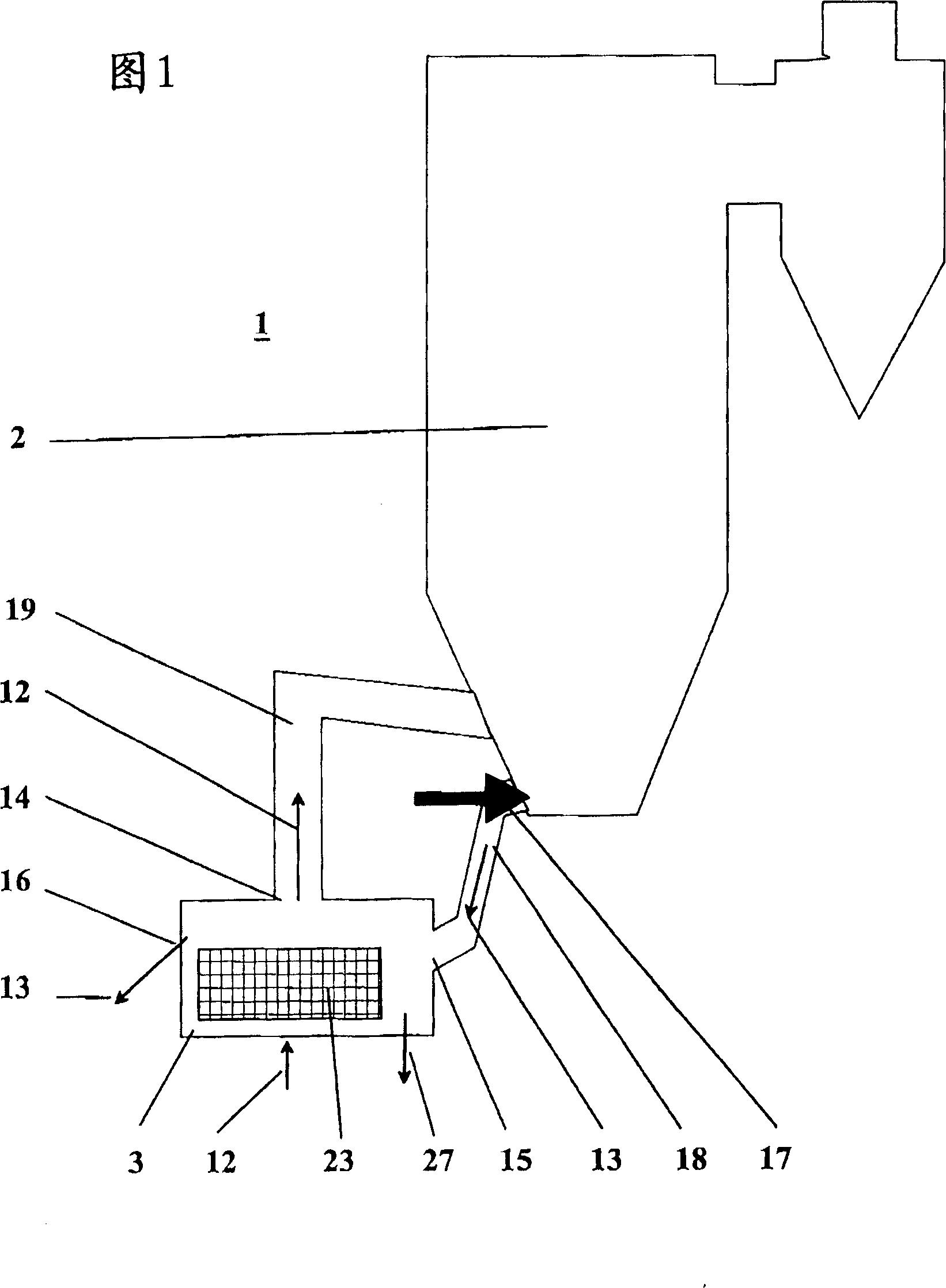
[0034] Figure 1 schematically shows a circulating fluidized bed reactor 1 having a reactor chamber or combustion chamber 2 in which solid lump fuels, such as coal, waste, biomass, etc., are combusted in the fluidized bed, and having A fluidized bed cooler or solid matter cooler 3 connected to the combustion chamber 2 . The ash 13 produced during the combustion accumulates for the most part on the bottom of the combustion chamber 2 and the remainder of the ash flows out of the combustion chamber 2 and is removed via the fluidized bed cooler 3 . The ash 18 flows out of the combustion chamber 2 via a cooler filling line 18 , which connects the combustion chamber 2 via a solids inlet 15 to the cooler 3 . An ash regulating fitting 17 is arranged at the outlet of the combustion chamber 2 to regulate the flow 13 of solid matter flowing out into the cooler 3 .

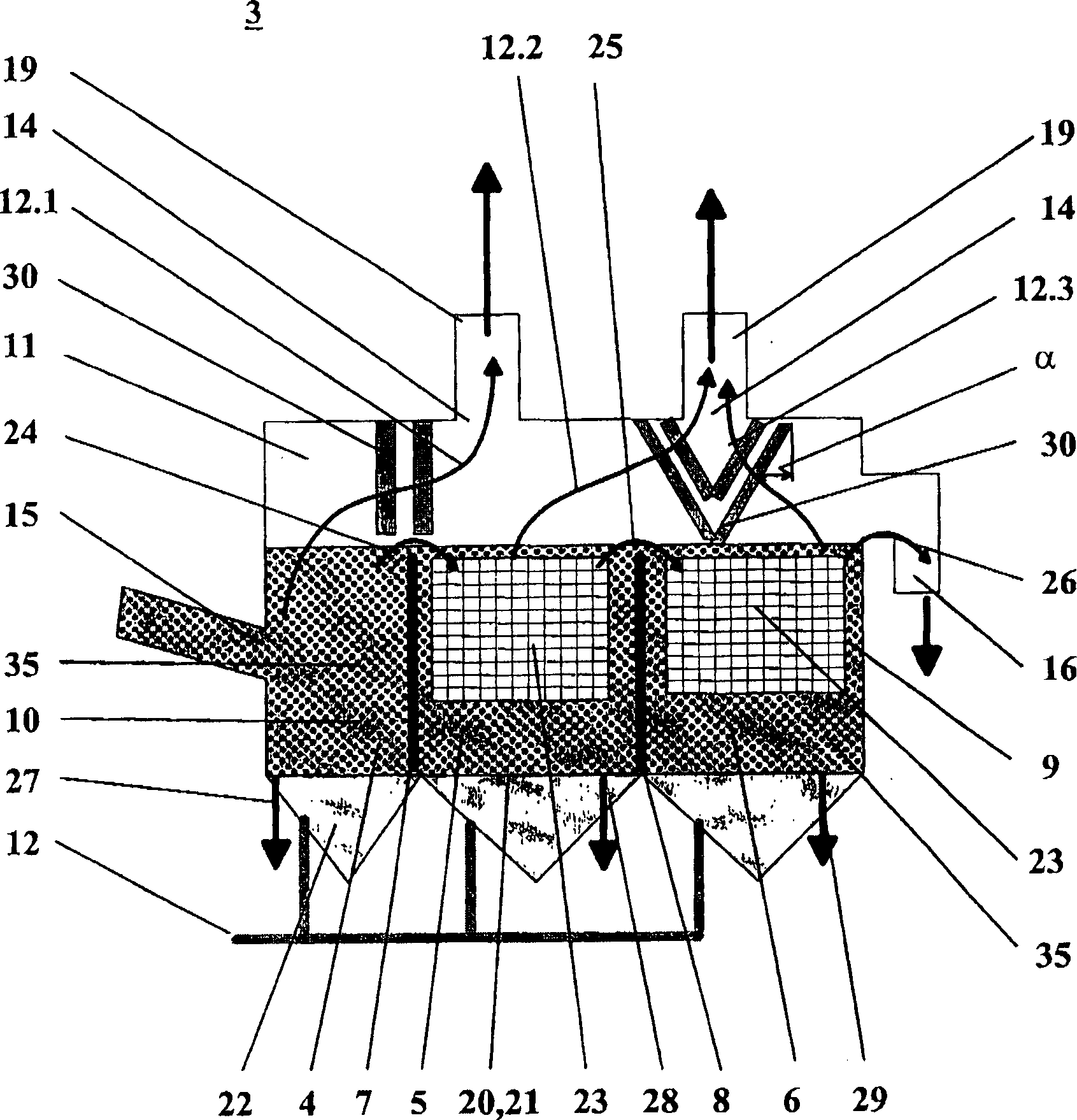
[0035] In order to cool the ash or solid matter 13, the fluidized bed cooler 3 is provided with one or more swirl chambers ...


PUM


Abstract

Circulating fluidized bed reactor especially for burning fuel, includes a combustion chamber (2) having a bed with fluidized solid particle materials therein and a solid matter cooler (3) connecting with it used for cooling the expellent ash or the solid matter (13) from the bottom of the combustion chamber (2). The cooler (3) includes: at least a turbulence chamber (4, 5, 6) used to make the to be chilled solid matter pass through in a horizontal flow, wherein the first turbulence chamber (4, 5, 6) has a inferior part (10) and a free space (11) arranged above the cooler fluidized bed (35) communicating with the gas side and the solid matter side of the corresponding turbulence chamber (4, 5, 6); an apparatus used for inputting the fluidizing agent (12) to each inferior part (10) to in order to fluidize the granular material in the turbulence chamber (4, 5, 6); at least a discharge opening (14), used for draining the fluidizing agent (12) from the free space (11) into the inferior part of the combustion chamber (2); at least an inlet port (15), connecting the first turbulence chamber (4) to the inferior part of the combustion chamber (2), used for inducting the ash (13) from the bottom vicinity of the fluidized bed firing furnace into the cooler (3); and at least a discharge opening (16), connecting with the final turbulence chamber (4, 5, 6), used for separating the solid matter grain (13) from the fluidizing agent (12) containing the solid matter grain (13) flowing in the direction of the discharge opening (14) and returning the separated solid matter (13) to the turbulence chamber (4, 5, 6).

Description

technical field [0001] The present invention relates to a circulating fluidized bed reactor, in particular for the combustion of fuels, and to a method for operating a circulating fluidized bed reactor. Background technique [0002] Such fluidized bed reactors are used in particular in energy technology or power plant technology. Therein, coal or other combustible materials, such as waste or biomass, are burned in a fluidized bed in a reactor chamber or combustion chamber. In order to separate and cool the ash or solid matter produced during the combustion of the fuel, the lower region of the combustion chamber is connected to an ash cooler or solid matter cooler. As solid matter coolers, mechanical coolers such as serpentine cooling pipes, cooling vibrating launders, etc., as well as coolers with a stationary fluidized bed such as fluidized bed coolers, ash screening machines, separation coolers are known Wait. [0003] Such fluidized bed coolers or solid matter coolers,...

Claims


Application Information

Patent Timeline
Patent Type & Authority Applications(China)
IPC IPC(8): F23C10/24B01J8/18
CPCF23J1/00F23D1/00F28D13/00F22B31/0061F23J2900/01002
Inventor 贝恩德·克罗默尔约阿希姆·泽贝尔贝恩德·塔勒尔
Owner ALSTOM TECH LTD
Why Eureka
Try Eureka