Inflator
An inflator, pressurized gas technology, applied in the direction of vehicle safety arrangement, pedestrian/occupant safety arrangement, transportation and packaging, etc., can solve the problem that the inflator is not suitable for use with very limited installation space, the overall size of the inflator is increased, etc. problems, resulting in improved productivity, reduced size and weight, and increased fixing strength
- Summary
- Abstract
- Description
- Claims
- Application Information
AI Technical Summary
Problems solved by technology
Method used
Image

Examples
no. 1 example
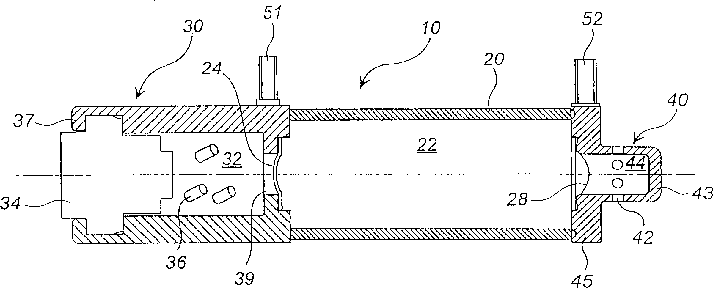
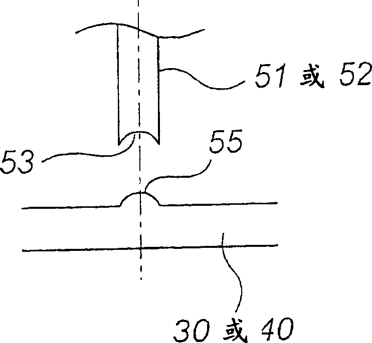
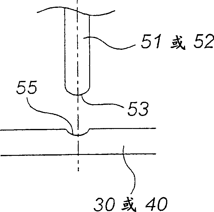
[0049] figure 1 is the axial sectional view of the inflator, while Figure 2(a)~2(d) It is a view explaining how to attach stud bolts.
[0050] The inflator 10 includes a cylindrical shell 20 with both ends open, a first casing 30 attached to the open portion of one end of the cylindrical shell 20, and a first cover 30 attached to the open portion of the other end of the cylindrical shell 20. The second casing 40 .
[0051] Pressurized gas such as argon, helium or nitrogen used as an airbag inflation medium is filled into a sealed space (ie, a pressurized gas chamber) 22 surrounded by the cylindrical case 20 , the first case 30 and the second case 40 . The maximum pressure setting for filling pressure is approximately 70,000kPa
[0052] The cylindrical case 20 is made of steel or the like, and has a circumferential wall of constant thickness. The cross-section of the housing is not limited to a circle, but may be polygonal or elliptical.
[0053] The interior of the first...
no. 3 example
[0076] Figure 4 It is an axial cross-sectional view of the inflator (inflator 100 ), and is also used as an explanatory view of an airbag attachment method.
[0077] The cylindrical case 112 has an opening 114 at one end thereof, and is closed at the other end thereof. An inert gas such as argon, helium, nitrogen, etc. is filled into the closed space (ie, the pressurized gas chamber) at a maximum pressure of about 70,000 kPa. With respect to the axial direction, the cylindrical housing 112 has a circular cross section, and the opening portion 114 has a similar circular cross section.
[0078] The studs 151 , 152 are fixed to the circumferential wall (of constant thickness) of the cylindrical housing 112 using resistance welding. The studs 151 , 152 are arranged on the same line along the axial direction of the inflator 100 and extend in a direction perpendicular to the axial direction.
[0079] In order to increase the welding strength, the circumferential walls of the stu...
no. 4 example
[0095] Figure 5 is a side view of the aerator configured with brackets, Image 6 is a magnified view of the bracket, while Figure 7(a) ~ 7(c) It is a schematic view showing the fixing process of fixing the bracket to the stud. It should be pointed out that in Figure 5 In ~7, the same reference numerals represent figure 1 Or the same elements and structures as the inflator shown in Figure 2, so their introduction is omitted.
[0096] exist Figure 5 Among them, two studs 51, 52 are sequentially formed on the side (that is, the peripheral surface) of the inflator housing 20 in the axial direction, while the other two studs 54, 56 are formed on the side of the housing opposite to the two studs 51. , 52 are set in the circumferential order. In other words, in the inflator of this embodiment, the two studs (( 51 , 54 ) or ( 52 , 56 )) that are lined up in the circumferential direction on the side of the case are arranged at on the two positions above. This type of aerato...
PUM
 Abstract
Description
Claims
Application Information
 - R&D
- Intellectual Property
- Life Sciences
- Materials
- Tech Scout
- Unparalleled Data Quality
- Higher Quality Content
- 60% Fewer Hallucinations
Browse by: Latest US Patents, China's latest patents, Technical Efficacy Thesaurus, Application Domain, Technology Topic, Popular Technical Reports.
© 2025 PatSnap. All rights reserved.Legal|Privacy policy|Modern Slavery Act Transparency Statement|Sitemap|About US| Contact US: help@patsnap.com