Cutting tool clamp and cutting tool

A technology for cutting blades and cutting tools, which is applied in the direction of manufacturing tools, tool holder accessories, milling cutters, etc., can solve the problems of prolonging working hours and increasing working costs, and achieve the effect of reducing weight, reducing weight and reducing production costs

Inactive Publication Date: 2007-02-21
NGK SPARK PLUG CO LTD
View PDF1 Cites 12 Cited by
  • Summary
  • Abstract
  • Description
  • Claims
  • Application Information

AI Technical Summary

Problems solved by technology

Since the time required to change blades is downtime, it increases operating time, which in turn leads to higher operating costs

Method used


Image

  • Cutting tool clamp and cutting tool
  • Cutting tool clamp and cutting tool
  • Cutting tool clamp and cutting tool

Examples


no. 1 example

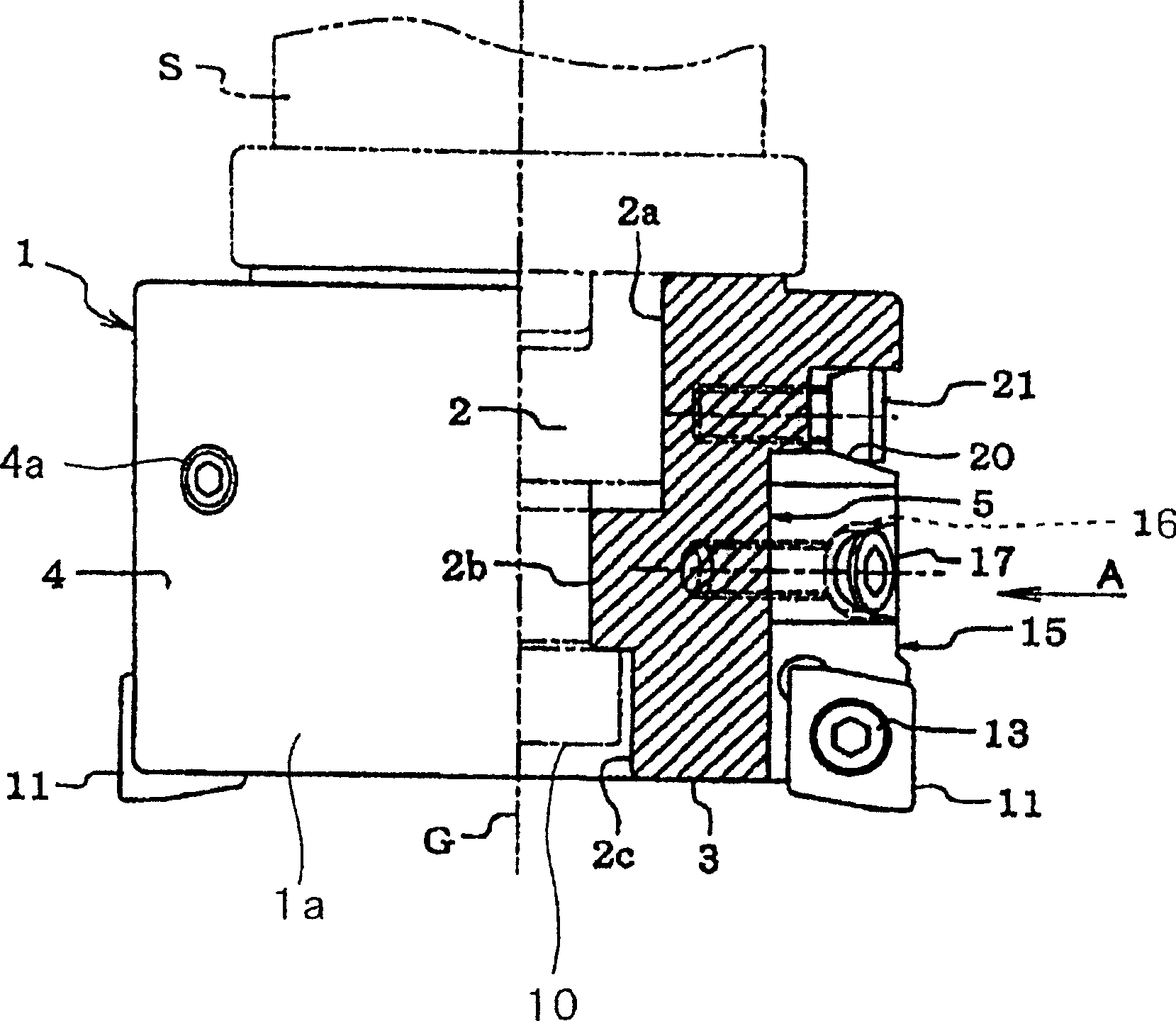
[0160] We will detail one of the best embodiments of the cutting insert holder and cutting tool and use as an example a rotating cutting tool which is a face milling cutter such as Figure 1-4 shown.

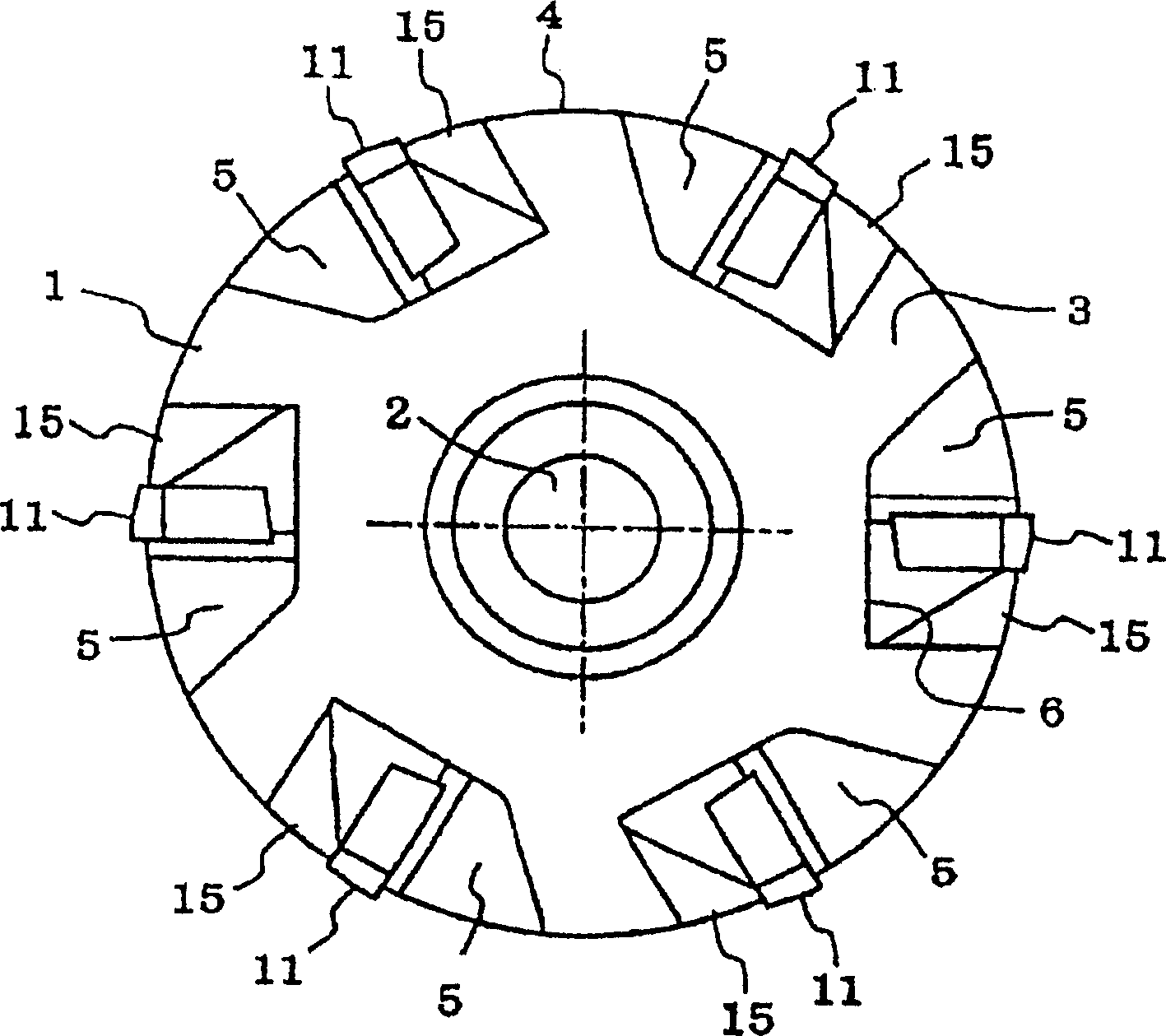
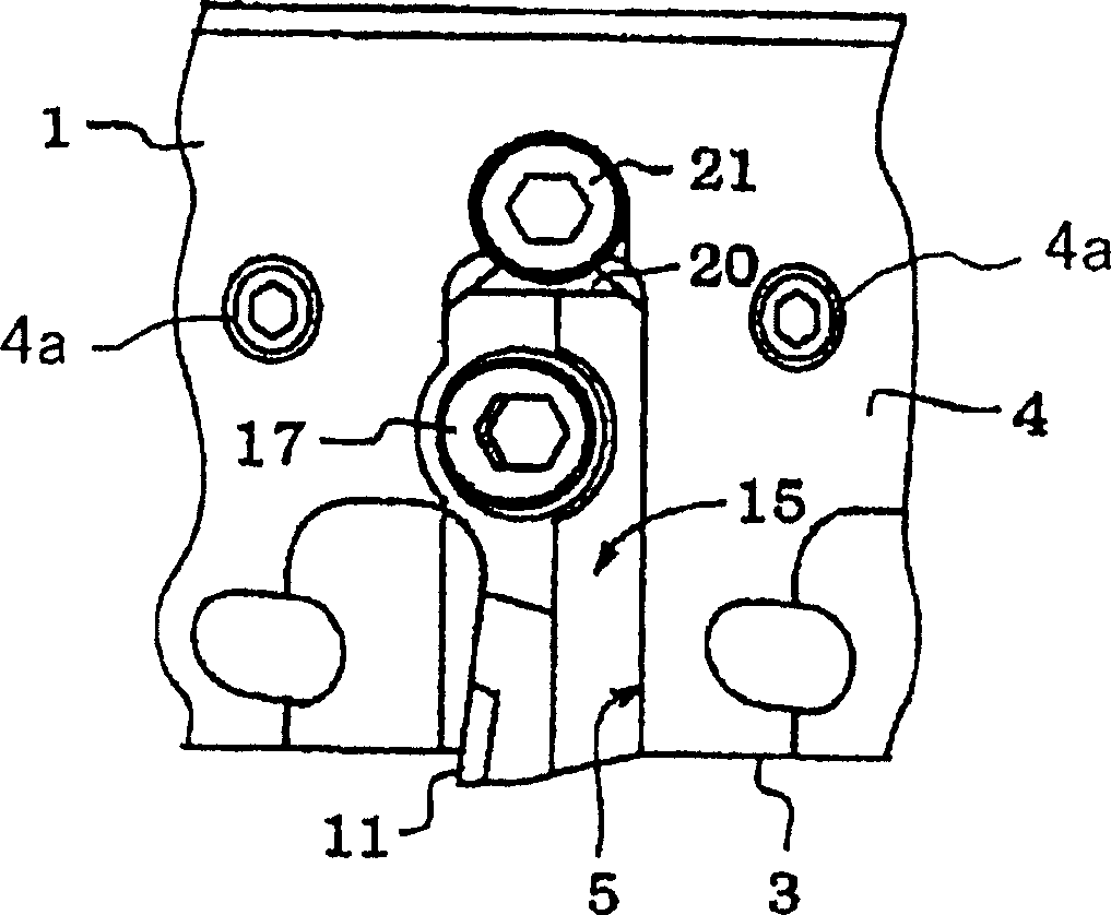
[0161] figure 1 is a partial cutaway front view of a rotary cutting tool. figure 2 yes figure 1 Bottom plan view of the rotary cutting tool in . image 3 is when viewed in the direction of arrow A figure 1 Partial side view of the tool in . Figure 4 is an enlarged view showing an internally threaded member, which is a threaded coil, such as HELI-SERT(R) or Heli-Coil(R) in this example, fixedly embedded in the cutting insert holder.

[0162] In the drawings, reference numeral 1 denotes a plastic rotary cutting blade holder. The types of plastics and the method of producing the cutting insert holder 1 will be described later in this embodiment.

[0163] as by figure 1 with 2 As can be seen in , the cutting insert holder 1 has a cylindrical base 1a. In the central part ...


PUM


Abstract

This invention provides a cutting tool having a cutting insert holder which has a lighter weight and can be produced at a lower cost than that made of aluminum. The base of the cutting insert holder, to which at least one cutting insert is fixed, is made of an amorphous plastic including from 30% to 60% of glass fiber. The cutting insert holder has at least one female-screw member, such as a screw thread coil (e.g. a HELI-SERT TM or Heli-Coil TM insert), which has a screw tap for securing an adjusting member, to which a cutting insert has been fixed, to the base by screw-driving of a hexagon socket head cap bolt. The female-screw member is fixedly embedded in the inner end of an insert-holding recess formed in the base.

Description

technical field [0001] The present invention relates to cutting blade holders for rotating tools and rotating cutting tools, and to cutting tools provided with a cutting blade holder on which at least one cutting blade such as a non-resharpening tip is fixed, and which cutting tool is suitable for use in Face milling cutters and boring bars used in multi-process automatic numerically controlled machine tools. Hereinafter, a cutting tool may be simply referred to as a tool. Background technique [0002] Cutting insert holders for turning tools and rotary cutting tools are usually manufactured by machining round stock obtained by cutting round bars (also known as round bars) of ferrous metals such as steel or square bars of the same metal of. The reason for using steel as a material is that it has appropriate strength, workability, and impact resistance to impacts that a cutting insert holder receives when used in a cutting tool, and is economically advantageous. However, w...

Claims


Application Information

Patent Timeline
Patent Type & Authority Applications(China)
IPC IPC(8): B23C5/20B23C5/06B23B29/00
Inventor 熊切孝之伊藤正义新藤知昭
Owner NGK SPARK PLUG CO LTD
Why Eureka
Try Eureka