Thermal safety battery and method for making same
A safety and battery technology, which is applied in the manufacture of electrolyte batteries, secondary batteries, battery pack components, etc., can solve the problems of poor thermal safety of batteries, achieve the effect of preventing large-area instantaneous short circuit, remarkable effect, and simple operation
- Summary
- Abstract
- Description
- Claims
- Application Information
AI Technical Summary
Problems solved by technology
Method used
Image
Examples
preparation example Construction
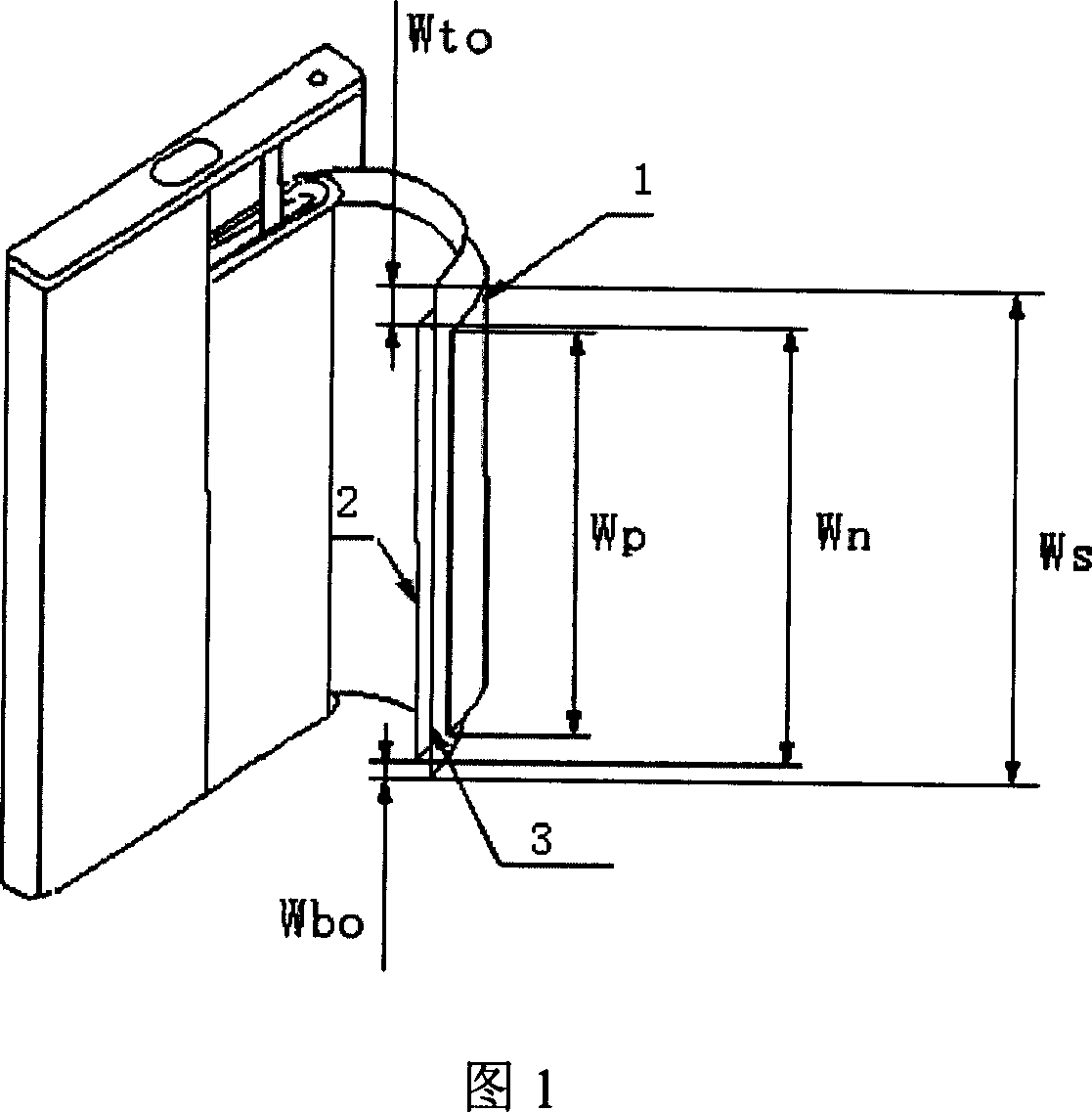
[0026] The present invention also provides a method for preparing the above-mentioned thermally safe battery, which includes preparing the positive electrode sheet and the negative electrode sheet of the battery, and fixing one end of the positive electrode sheet, the negative electrode sheet, and the diaphragm layer through adhesive tape to prepare an electrode group, and then the obtained electrode The group and the electrolyte are sealed in the battery case, wherein the width relationship of the positive electrode sheet, the negative electrode sheet and the separator layer satisfies W to ≥3 mm, and W n ≥W p , where W to =W s -W n -W bo , W n Represents the width of the negative plate, W p Represents the width of the positive plate, W s Represents the width of the diaphragm layer, W to Represents the exposed width of one end of the diaphragm layer, W bo Represents the exposed width of the other end of the diaphragm layer, preferably W to = 3-15 mm. Usually, W bo ...
Embodiment 1
[0032] This embodiment is used to illustrate the lithium ion secondary battery provided by the present invention and its preparation method.
[0033] (1) Preparation of positive electrode sheet
[0034] 100 g LiCoO 2 , 5 grams of conductive agent acetylene black and 5 grams of adhesive polyvinylidene fluoride (PVDF) are uniformly mixed in 55 ml of N-methylpyrrolidone (NMP) and then evenly coated on both sides of an aluminum foil with a thickness of 20 microns. After 120 ° C Dried in a vacuum oven, rolled, and cut into pieces to obtain a length of 370 mm and a width of 43.0 mm (W p ), a positive electrode sheet with a thickness of 140 microns. The amount of coating is such that each positive electrode sheet contains 5.8 grams of LiCoO 2 .
[0035] (2) Preparation of negative electrode sheet
[0036] 100 grams of negative electrode active material artificial graphite and 9 grams of binder PVDF are uniformly mixed in 45 milliliters of NMP, and then evenly coated on both side...
Embodiment 2
[0040] This embodiment is used to illustrate the lithium ion secondary battery provided by the present invention and its preparation method.
[0041] (1) Preparation of positive electrode
[0042] 100 g LiCoO 2 , 5 grams of conductive agent acetylene black and 5 grams of adhesive polyvinylidene fluoride (PVDF) are uniformly mixed in 55 ml of N-methylpyrrolidone (NMP) and then evenly coated on both sides of an aluminum foil with a thickness of 20 microns. After 120 ° C Dried in a vacuum oven, rolled, and cut into pieces to obtain a length of 370 mm and a width of 42.0 mm (W p ), a positive electrode with a thickness of 140 microns. Coated in such an amount that the resulting positive electrode contained 5.8 grams of LiCoO 2 .
[0043] (2) Preparation of negative electrode
[0044] 100 grams of negative electrode active material artificial graphite and 9 grams of binder PVDF are uniformly mixed in 40 milliliters of NMP, and then evenly coated on both sides on a copper foil ...
PUM
 Abstract
Description
Claims
Application Information
 - R&D
- Intellectual Property
- Life Sciences
- Materials
- Tech Scout
- Unparalleled Data Quality
- Higher Quality Content
- 60% Fewer Hallucinations
Browse by: Latest US Patents, China's latest patents, Technical Efficacy Thesaurus, Application Domain, Technology Topic, Popular Technical Reports.
© 2025 PatSnap. All rights reserved.Legal|Privacy policy|Modern Slavery Act Transparency Statement|Sitemap|About US| Contact US: help@patsnap.com

