Metal capacitor and manufacturing method thereof

A metal capacitor and manufacturing method technology, applied in the direction of capacitors, electrolytic capacitors, capacitor terminals, etc., can solve the problems of reduced reliability of capacitors, increased loss, low electrical conductivity, etc., achieve non-flammable environment tolerance, and improve heat-resistant safety. performance, improve electrical safety

Active Publication Date: 2009-04-22
KOREA JCC CO +1
View PDF0 Cites 3 Cited by
  • Summary
  • Abstract
  • Description
  • Claims
  • Application Information

AI Technical Summary

Problems solved by technology

[0006] Existing aluminum electrolytic capacitors use an electrolytic solution as the electrolyte, so there are problems of low conductivity, a significant increase in resistance in the high-frequency region, and an increase in the impedance of the capacitor
In addition, when the resistance of the capacitor is high, the high-frequency characteristics deteriorate, the ESR (Equivalent Series Resistance: Equivalent Series Resistance) becomes high, the reliability of the capacitor decreases, and there is a problem that the loss increases.
In addition, since the impedance becomes higher, the heat generated by the ripple current becomes higher, and smoke and combustion may occur, so there is a problem that safety and environmental resistance are not met.

Method used


Image

  • Metal capacitor and manufacturing method thereof
  • Metal capacitor and manufacturing method thereof
  • Metal capacitor and manufacturing method thereof

Examples


no. 1 example 》

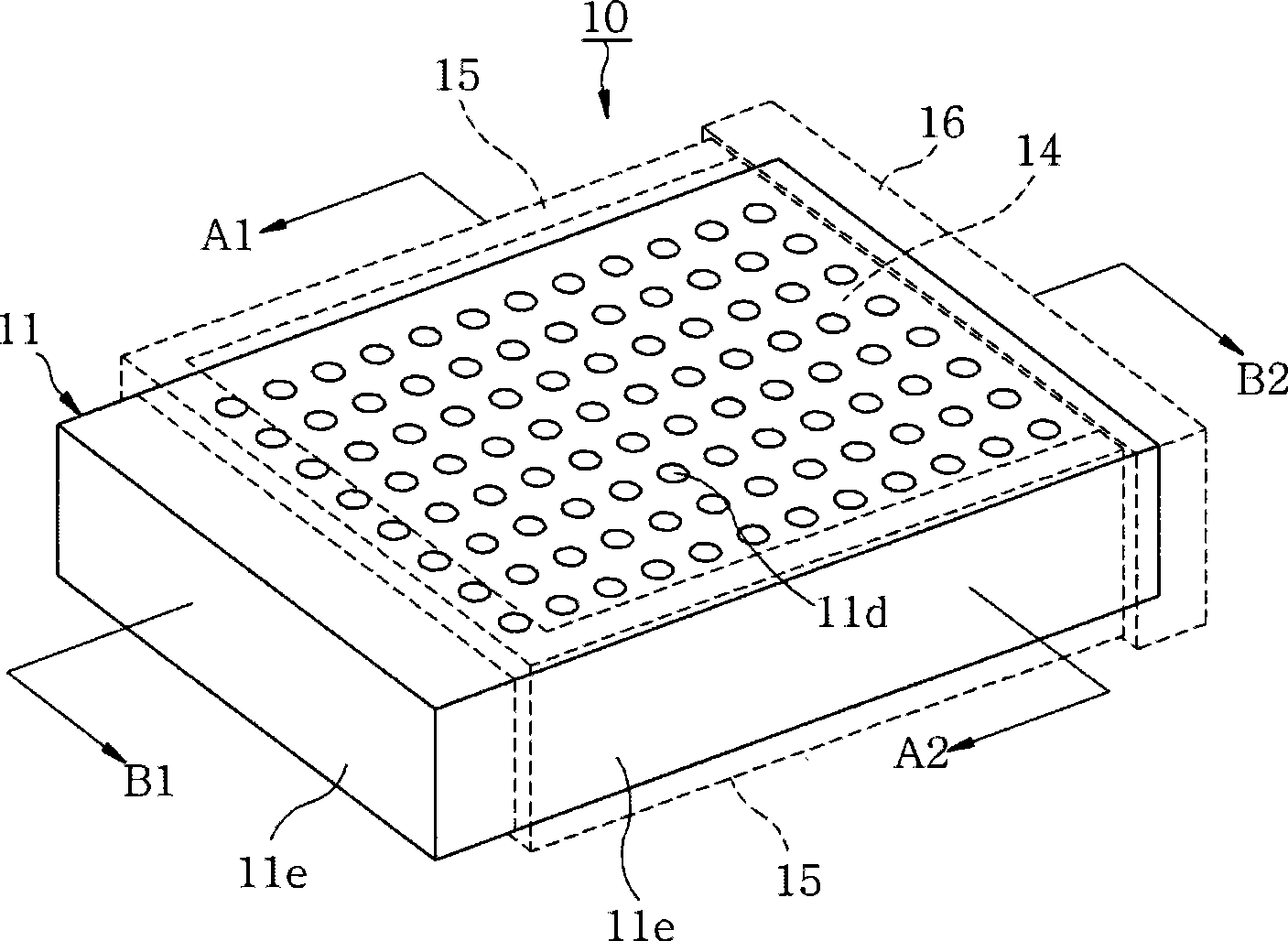
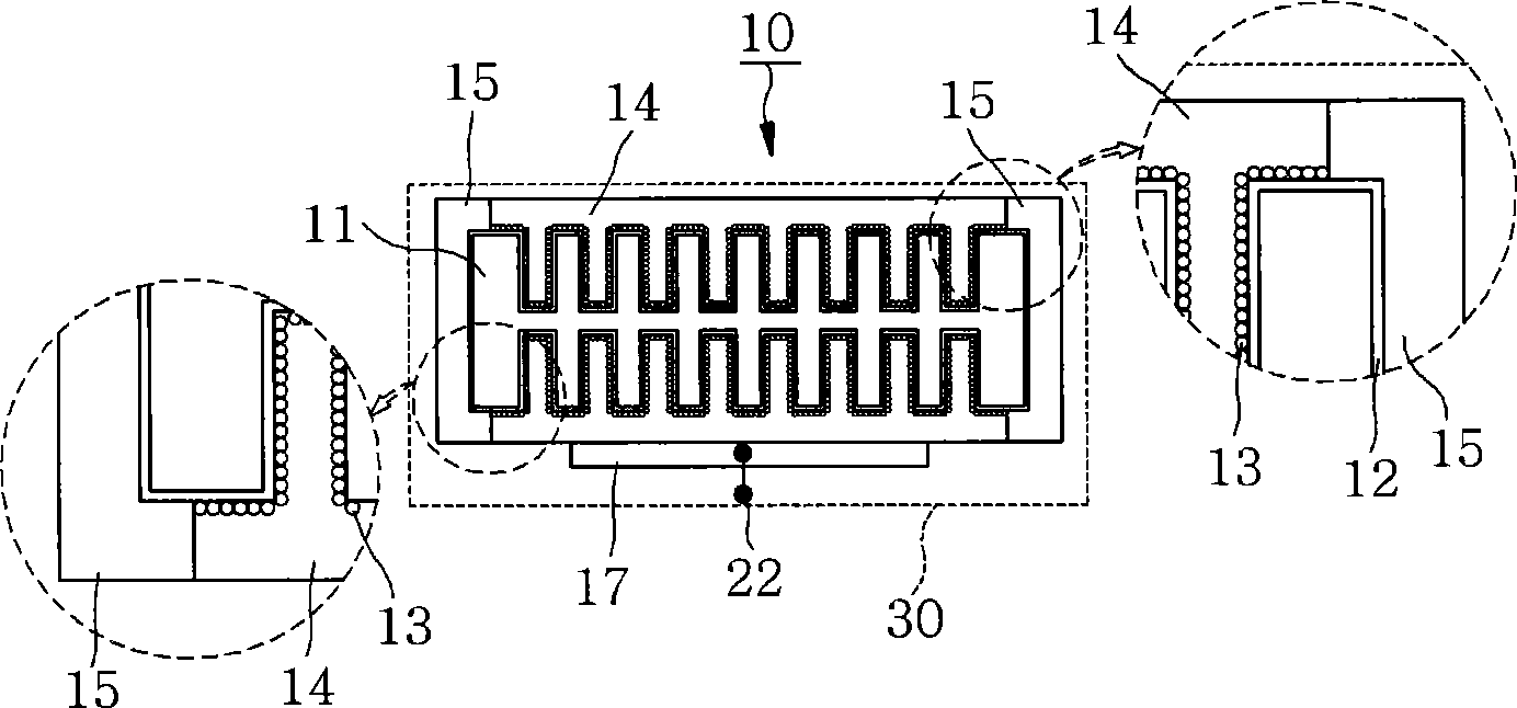
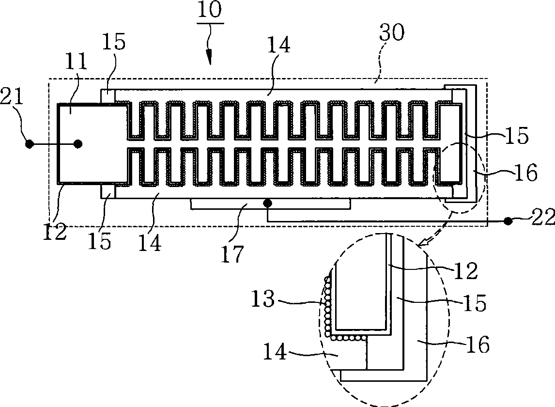
[0033] Refer to the following Figures 1 to 3 The description is as follows, Figures 1 to 3 A metal capacitor structure according to the first embodiment of the present invention is added.

[0034] figure 1 is a perspective view of a metal capacitor according to a first embodiment of the present invention, figure 2 yes figure 1 A cross-sectional view of the metal capacitor shown along line A1-A2, image 3 yes figure 1 A cross-sectional view of the metal capacitor shown along line B1-B2. Such as Figure 1 to Figure 3 As shown, the metal capacitor 10 according to the first embodiment of the present invention consists of a metal component 11, a metal oxide layer 12, a plurality of seed electrode layers 13, a plurality of main electrode layers 14, an insulating layer 15, a conductive connection layer 16, a first lead terminal 21, second lead terminal 22, and sealing member 30, but there are cases where the seed electrode layer 13 is not used depending on user needs. The ...

no. 2 example 》

[0060] The metal capacitor 110 will be described below with reference to the drawings. Among them, the metal capacitor 110 uses the non-through-type metal member 10a constituting the metal capacitor 10 according to the first embodiment of the present invention.

[0061] Such as Figure 5 As shown, the metal capacitor 110 according to the second embodiment of the present invention is composed of a plurality of non-penetrating metal parts 10a, a conductive adhesive layer 17, a third lead terminal 23, a fourth lead terminal 24, and a sealing member 30. The following sequence describes each structure.

[0062] Such as Figure 4g as well as Figure 4h As shown respectively, a plurality of non-penetrating metal parts 10a are composed of a metal part 11, a metal oxide layer 12, a plurality of seed electrode layers 13, a plurality of main electrode layers 14, an insulating layer 15, and a conductive connection layer 16. The detailed description has already been made in the descrip...

no. 3 example 》

[0069] Next, the metal capacitor 120 will be described with reference to the drawings. Among them, the metal capacitor 120 uses the non-through-type metal member 10a constituting the metal capacitor 10 according to the first embodiment of the present invention.

[0070] Such as Figure 6 As shown, the metal capacitor 120 according to the third embodiment of the present invention is composed of a plurality of non-penetrating metal parts 10a, a conductive adhesive layer 17, a first polarity lead terminal 25 and a second polarity lead terminal 26, and the following sequence describes each structure.

[0071] Such as Figure 4g as well as Figure 4h As shown respectively, a plurality of non-penetrating metal parts 10a are composed of a metal part 11, a metal oxide layer 12, a plurality of seed electrode layers 13, a plurality of main electrode layers 14, an insulating layer 15, and a conductive connection layer 16. The detailed description has already been made in the descriptio...


PUM

PropertyMeasurementUnit
diameteraaaaaaaaaa

Abstract

A metal capacitor in which an electric conductivity is significantly improved by applying a metal material for an electrolyte and a manufacturing method thereof is provided. The capacitor includes a metal member comprising a groove forming portion where a plurality of grooves is formed, an electrode withdrawing portion formed on the groove forming portion, and a sealing portion; a metal oxide layer being formed on the metal member; an insulating layer being formed on the metal member to expose the electrode withdrawing portion of the metal member; a plurality of main electrode layers, each main electrode layer being formed on the metal oxide layer that is formed on the groove forming portion of the metal member; and a conductive connecting layer being formed on the plurality of main electrode layers and the insulating layer to face the electrode withdrawing portion of the metal member and connect the plurality of main electrode layers, wherein a lead terminal is connected to the electrode withdrawing portion of the metal member and each of the main electrode layers.

Description

technical field [0001] The present invention relates to a metal capacitor and a manufacturing method thereof, and more particularly, to a metal capacitor using a metal material in an electrolyte to significantly improve conductivity and a manufacturing method thereof. Background technique [0002] Conventionally, aluminum electrolytic capacitors are known as capacitors used for filtering power output from a power supply circuit to a predetermined value or for low-frequency bypass, and the manufacturing method thereof is as follows. [0003] First, in order to increase the surface area of ​​the aluminum foil and thereby increase the capacitance, an etching process is performed on the surface of the aluminum foil. When the etching is complete, the molding process that forms the dielectric on the aluminum foil is performed. When the cathode and anode aluminum foils are manufactured respectively through etching and forming processes, the cutting process of cutting the manufactu...

Claims


Application Information

Patent Timeline
Patent Type & Authority Applications(China)
IPC IPC(8): H01G9/008H01G9/025H01G9/04
CPCH01G9/012H01G9/15H01G9/025
Inventor 吴英宙
Owner KOREA JCC CO
Why Eureka
Try Eureka