Rolling membrane retaining module set

A technology of rolling elements and modules, applied in the direction of bearing elements, linear motion bearings, bearings, etc., can solve problems such as cylinder deformation, finished product deformation, and mass production

Inactive Publication Date: 2007-03-07
HIWIN TECH
View PDF0 Cites 5 Cited by
  • Summary
  • Abstract
  • Description
  • Claims
  • Application Information

AI Technical Summary

Problems solved by technology

In this rolling element chain 41, although the rolling element 11 can be positioned in the Q direction and the L direction, the single holding element 411 cannot position the rolling element 11 in the vertical direction, so the rolling element is easy to fall, which is a huge problem in assembly. When walking on the return path, the rolling element 11 is very likely to jump out of the space when turning, and get stuck in the return path
[0003] Fig. 8 is a retainer design that connects many individual individuals. The joint retainer in the figure connects the spacer blocks 511 with a flexible link chain 512, so that each rolling element 11 is placed in the space between the two spacer blocks 511 to roll. Assembling the spacer block 511 and the connecting chain 512 requires a lot of manpower to assemble. In addition, the rolling element 11 also requires manpower to assemble. It is not easy and time-consuming to assemble such a small-sized element itself.
If the spacer block 511 and the connecting chain 512 are designed as one body, from the perspective of mold design, the spacer block 511 is concave, so barbs must be produced during demoulding (that is, the mold core and components cannot be released smoothly due to interference. ), forced demoulding has size limitations, and it is very likely to cause component deformation, so the design of the retainer in Figure 8 still has shortcomings to be overcome
[0004] Figure 9 belongs to the rolling element holding chain, in which the holding chain 61 is connected by a connecting chain 612 on both sides of the spacer plate 611. Although it has the ability to open the mold, the biggest difficulty lies in the round hole 613 on the spacer plate 611. From the design point of view, it is necessary to introduce a cylinder with a small diameter and a long length. When the finished product is to be ejected after injection molding, the cylinder must be pulled out first. At this time, a complicated transmission mechanism must be used to export the cylinder. However, The finished product will be tightly wrapped with the cylinder after cooling and shrinking, making it more difficult to pull out. At the same time, the action of pulling away will cause deformation of the finished product, and the cylinder will also have deformation problems after several times of entry and exit; secondly, in injection molding, The injection pressure is quite high, and such a slender cylinder is easily deformed or broken by the strong pressure. Therefore, the configuration of the rolling element in Figure 9 to maintain the chain 61 is not mass-producible, and the development of the mold is expensive and complicated.

Method used


Image

  • Rolling membrane retaining module set
  • Rolling membrane retaining module set
  • Rolling membrane retaining module set

Examples


Embodiment Construction

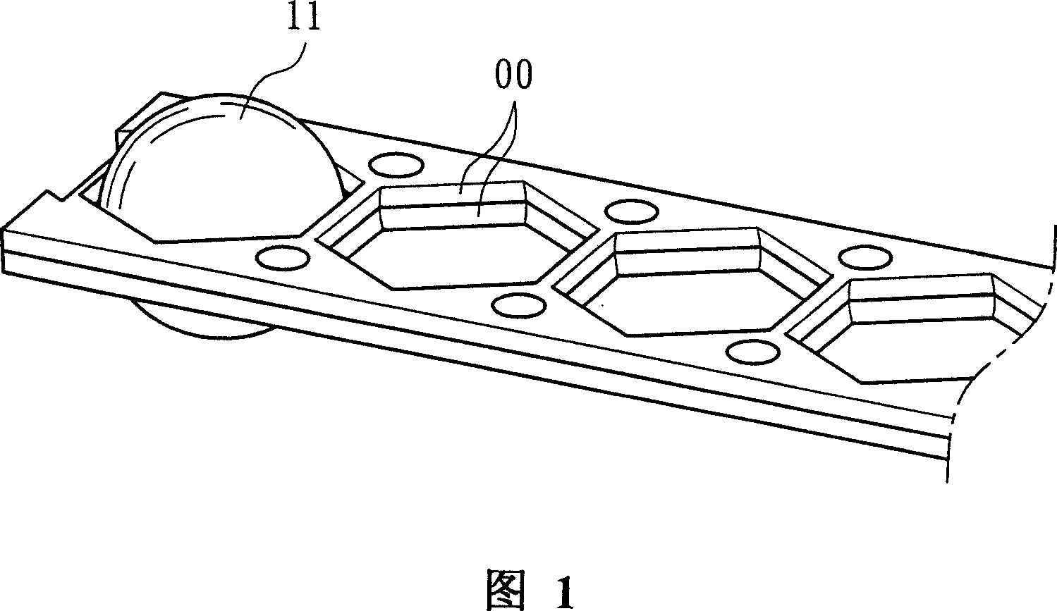
[0029] Please refer to Figure 1, which is a conceptual diagram of the space structure of the first embodiment of the rolling element holding module provided by the present invention:

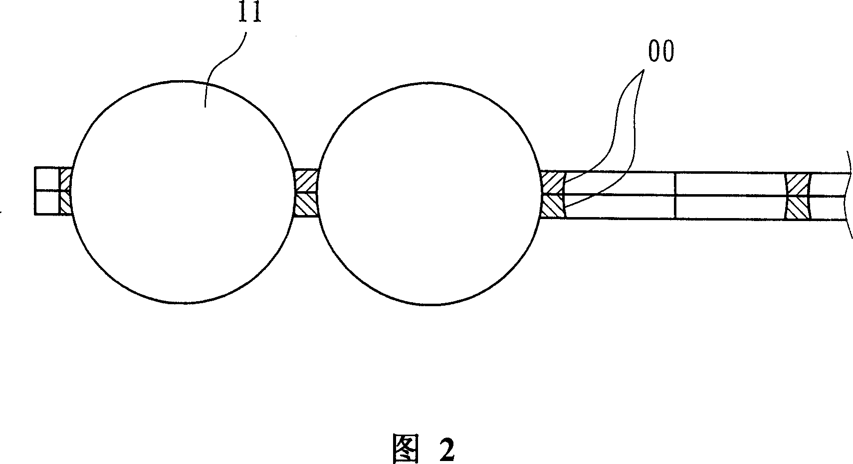
[0030] The rolling element 11 in the figure is positioned by the rolling element holding contact surface 00 of hexagonal structure (honeycomb structure). Fig. 2 is a sectional view of Fig. 1. It can be seen from Fig. 2 that the rolling element 11 is in tangential contact with all the rolling element maintaining contact surfaces 00, which can effectively reduce the friction caused by the rolling element 11 rolling with the rolling element maintaining contact surface 00. The frictional force enables the rolling element 11 to maintain the steering function of rolling.

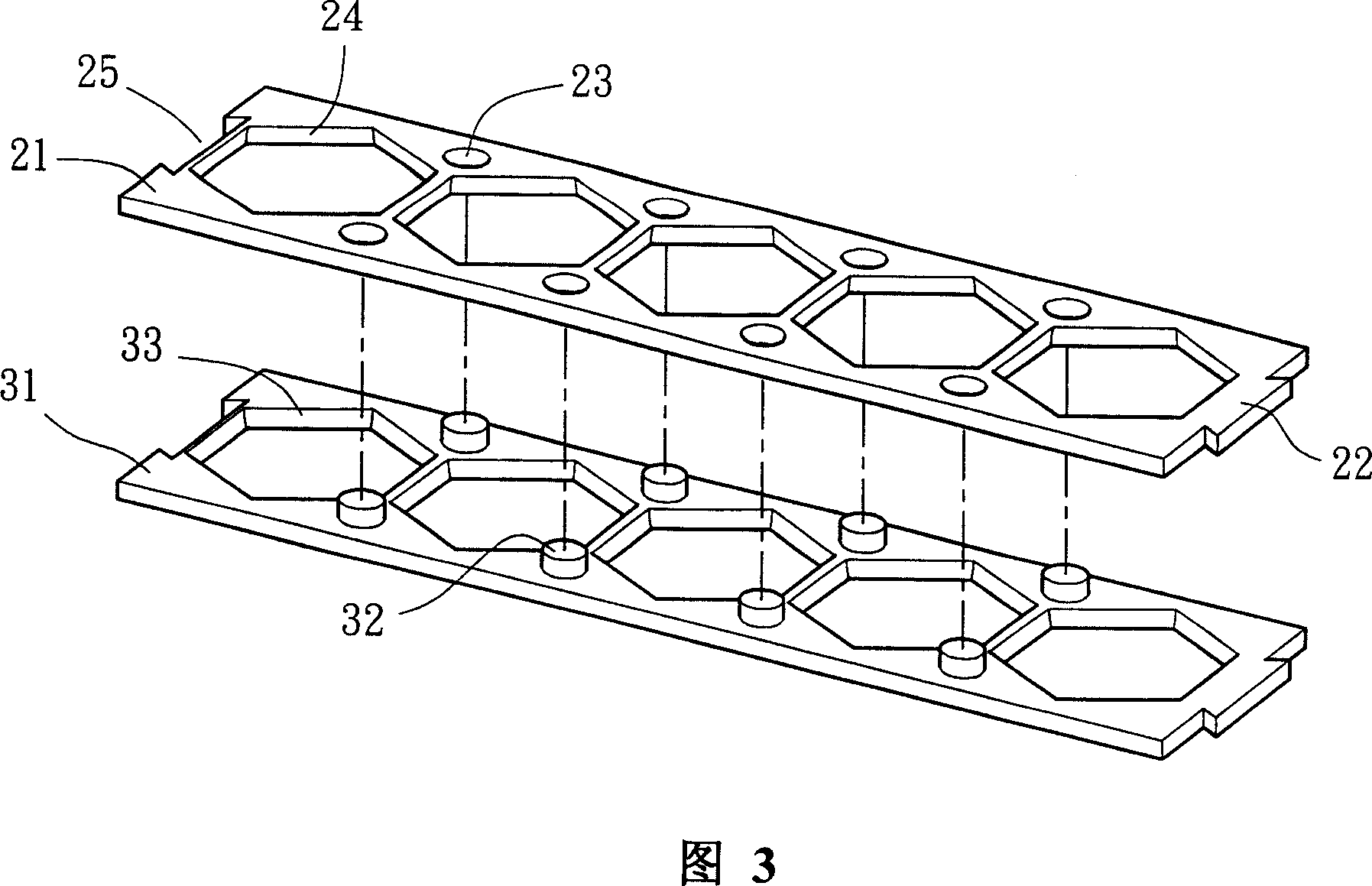
[0031] However, this design expects to be rapidly manufactured by injection molding. If the molded product is to be produced as a single component, it is not feasible in the mold development design. The reason is that the rolling el...


PUM


Abstract

This invention discloses one roller parts keeping mode set, which is characterized by the following: setting upper and down thin board combination parts with isolation space by use of beehive structure as rolling parts for effective positioning without over friction limitation due to the beehive structure on rolling parts.

Description

technical field [0001] The invention relates to a rolling element holding module, in particular to a rolling element holding device applied to a linear transmission element; generally speaking, the linear transmission element is applied to the mechanisms of machine tools, electronics, automation equipment, and semiconductor equipment. Background technique [0002] The traditional rolling element chain is shown in Figure 7, and each rolling element 11 of its rolling element chain 41 can be placed in the space 413, and the combination chain 412a is used between the two linking chains 412b to combine to form a prolate chain. 412a includes at least one retaining element 411 so that each rolling element 11 can be positioned by the retaining element 411 when rolling in the space 413 . In this rolling element chain 41, although the rolling element 11 can be positioned in the Q direction and the L direction, the single holding element 411 cannot position the rolling element 11 in th...

Claims


Application Information

Patent Timeline
Patent Type & Authority Applications(China)
IPC IPC(8): F16C33/38F16C29/06
Inventor 潘柏霖
Owner HIWIN TECH
Why Eureka
Try Eureka