Heat pipe hot pump composite drying power source system

A power source system and composite technology, applied in heat recovery systems, drying, dryers, etc., can solve problems such as combination difficulties, and achieve the effects of no environmental pollution energy, wide application range, and reduced energy consumption.

Inactive Publication Date: 2007-03-07
QINGDAO UNIV
View PDF0 Cites 9 Cited by
  • Summary
  • Abstract
  • Description
  • Claims
  • Application Information

AI Technical Summary

Problems solved by technology

The main reason is that there are still some difficulties in the combination of the existing heat pipe form and heat pump technology. At the same time, there are still many problems that need to be analyzed and discussed in a scientific and reasonable way.

Method used


Image

  • Heat pipe hot pump composite drying power source system
  • Heat pipe hot pump composite drying power source system
  • Heat pipe hot pump composite drying power source system

Examples


Embodiment 1

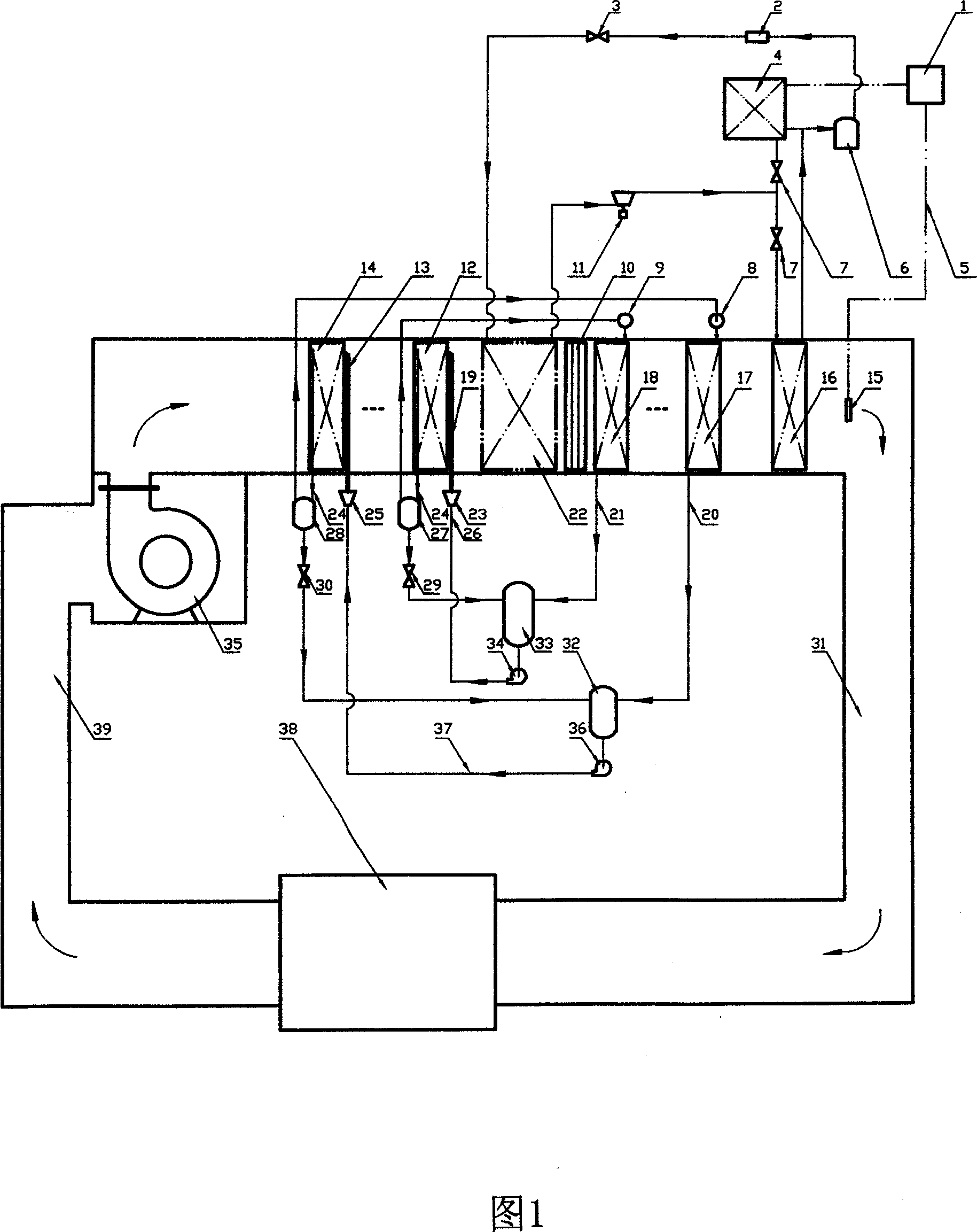
[0033] Embodiment 1: Figure 1 is a fully closed circulation type, with a total of n heat pipe cooling capacity recovery subsystems, the closest to the heat pump subsystem is the inner circulation heat pipe cooling capacity recovery subsystem, and the farthest from the heat pump subsystem is the outer circulation heat pipe cooling capacity recovery subsystem. The whole system is composed of a heat pump subsystem, n (1≤n≤20) heat pipe cooling capacity recovery subsystem, water baffle 10, air flow subsystem, air supply temperature control subsystem, drying room (or drying room) 38, etc. . The heat pump subsystem has one evaporator 22 in total, and its condenser is composed of an internal condenser 16 and an external condenser 4 connected in parallel, and the flow distribution ratio in the internal and external condensers is adjusted through two flow regulating valves 7; the power of the fan 35 Under the action, the air first flows through the evaporator 14 of the outer circulati...

Embodiment 2

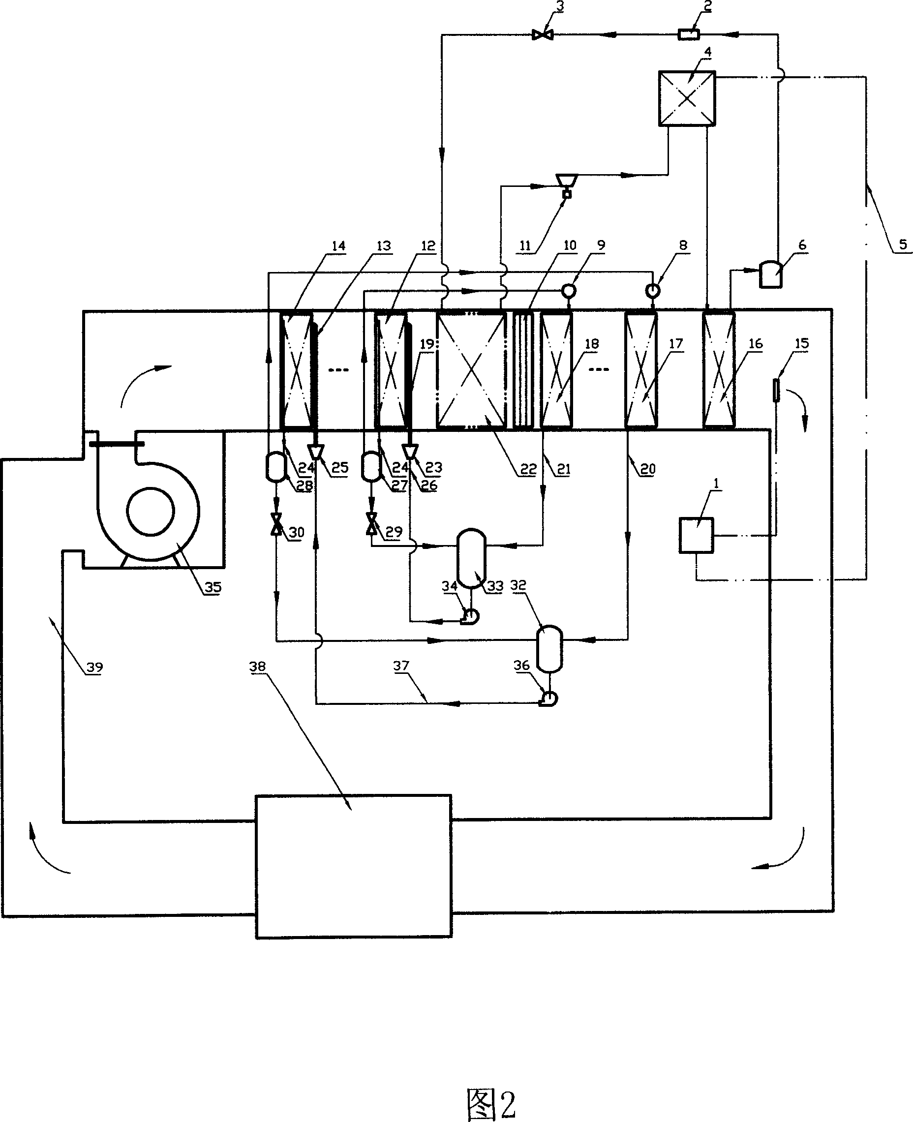
[0037] Embodiment 2: The structure of Fig. 2 is basically the same as that of Embodiment 1. The difference is the connection mode of the inner and outer condensers in the heat pump subsystem. The inner and outer condensers in Embodiment 1 are connected in parallel. Through two The flow regulating valve 7 is used to properly adjust the distribution of internal and external heat, while the internal and external condensers in Embodiment 2 are connected in series, and the flow rates in the two condensers are the same, and the energy distribution is realized entirely by adjusting the heat taken away by the external condenser. balance. The start-up and operation process of the system device is the same as that of Embodiment 1.

Embodiment 3

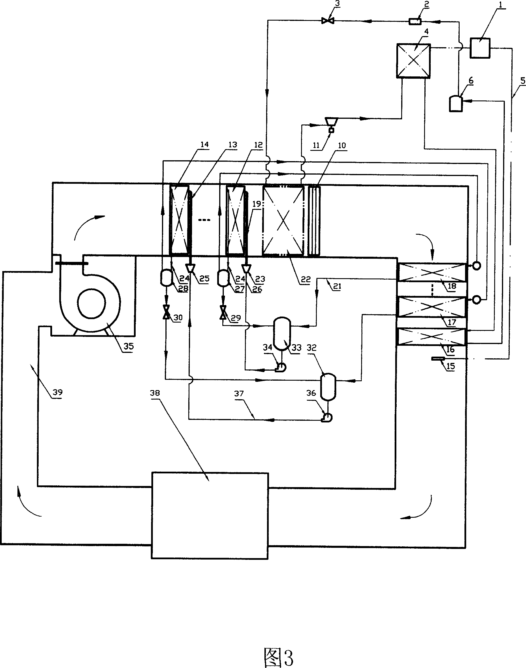
[0038] Embodiment 3: Fig. 3 is a fully closed circulation type, which is basically the same structure as Embodiment 2, but the arrangement is different. In Embodiment 2, the condenser of the heat pipe cold recovery subsystem and the condenser of the heat pump subsystem are arranged vertically, while in this embodiment, the condenser of the heat pipe cold recovery subsystem and the condenser of the heat pump subsystem are all arranged horizontally. The way it is arranged. The start-up and operation process of the system device is the same as that of Embodiment 1.


PUM


Abstract

This invention relates to energy saving technique field and to one heat tube pump compound dying and power system, which comprises m pieces of heat pump sub systems, n heat tube heat recycle sub system, water block board, air flow sub system, wind temperature control sub system, drying chamber, wherein, the heat tube cooling recycle sub system vapor device is fixed in front of heat pump sub system and water block board is fixed behind heat pump sub system.

Description

Technical field: [0001] The invention relates to the field of energy-saving technology, in particular to a high-efficiency energy-saving heat pipe heat pump composite drying power source system formed by organically combining heat pipe energy-saving technology and heat pump energy-saving technology. technical background: [0002] Drying operation involves a wide range of areas of the national economy. It is not only an indispensable basic production link for a large number of industrial and agricultural products, but also a large energy consumer in my country. The energy consumption accounts for about 12% of the total energy consumption of the national economy. In addition, the drying process causes Air pollution is often an important source of environmental pollution in our country, so the progress of drying technology is closely related to the development of the entire national economy. Drying is divided into two types: artificial drying and natural drying. All artificial d...

Claims


Application Information

Patent Timeline
Patent Type & Authority Applications(China)
IPC IPC(8): F26B23/10
CPCY02B30/52Y02B30/123
Inventor 田小亮孙晖
Owner QINGDAO UNIV
Why Eureka
Try Eureka