Method for detection and stopping leak for concrete buildings leakage source

A plugging method and building technology, applied in the field of measurement, can solve the problems of not knowing where to start, no reinforcement compensation, and insignificant effect, etc., and achieve the effect of excellent plugging effect, improved efficiency, and reinforcement reinforcement

Inactive Publication Date: 2007-03-07
李海军
View PDF0 Cites 42 Cited by
  • Summary
  • Abstract
  • Description
  • Claims
  • Application Information

AI Technical Summary

Problems solved by technology

If the tester does not have high knowledge of building structure and corresponding technology and experience, he often does not know where to start in actual operation. Even if the gas sensor captures a certain concentration of gas induction in a certain part, it may not be sure that the is the exact location of the leak
Second, because this measurement method uses local point measurement, the efficiency is low, and the effect is not significant in the diagnostic detection of large-area water leakage.
Although the Jiangtian-style plugging method is a relatively economical repair method, since it is only a plugging method that mainly fills gaps and cavities, it does not provide structural reinforcement for cracks in concrete. Reinforcement compensation for strength loss

Method used


Image

  • Method for detection and stopping leak for concrete buildings leakage source
  • Method for detection and stopping leak for concrete buildings leakage source
  • Method for detection and stopping leak for concrete buildings leakage source

Examples


Embodiment 1

[0042] A water leak occurred on the top of a flat-roofed industrial plant. The roof of the factory building is a membrane waterproof roof, and the roof structure layer is a prefabricated reinforced concrete slab, which is filled with fine stone concrete, and the concrete slab is leveled with a cement mortar leveling layer. A membrane waterproof layer is laid on the cement leveling layer, and finally 20mm thick cement mortar is used as the surface protection layer. After investigation, the location of the indoor water leakage point is near the downpipe and close to one side of the wall.

[0043] For the above leaks, take the following detection and plugging methods. The steps are:

[0044] The first step is visual inspection of the status quo.

[0045] First, conduct a field survey of the leaking condition of the indoor roof and the current status of the roof near the leaking location through visual observation. Grasp the indoor water leakage location is in the floor joints...

Embodiment 2

[0061] A certain concrete building had water leakage from the wall. Cracks were found at the leaking point of the indoor wall, and the outer wall was pasted with dark tiles, but no abnormal phenomenon could be seen by naked eye observation.

[0062] For the above example, the method of determining plugging is as follows:

[0063] The first step is visual inspection of the status quo.

[0064] Observe the situation of the indoor water leakage point. If there is a plaster layer on the surface of the water leakage point, remove it so as to observe the actual conditions such as cracks, cracks or honeycombs in the concrete pouring wall.

[0065] The second step is to record the status quo.

[0066] Use a thermal imaging camera to determine the condition of the exterior walls near the water leak. Mark the area where the temperature is abnormal.

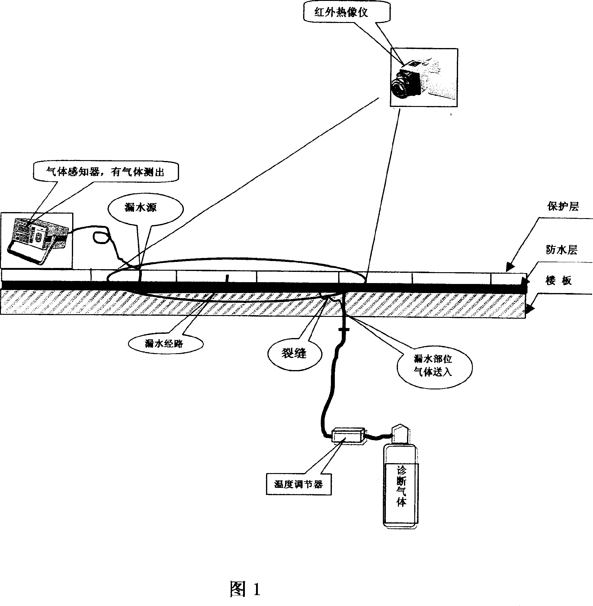
[0067] The third step is to measure the change of air delivery.

[0068] Send variable-temperature carbon dioxide gas from the indoor ...


PUM


Abstract

This invention belongs to measurement technique field and fixing technique field which is suitable for concrete architecture water leakage test method, which comprises the following steps: sending carbon dioxide gas from the leakage part on the architecture; then testing the gas outside the architecture and judging the leakage source according to the gas sensor situation; injecting the liquid emulsion into the leakage path crack or honeycomb hollow part to seal the leakage, which is characterized by adopting the infrared sense for analysis technique testing to judge the leakage source; adopting pressure injection to seal the leakage separately.

Description

technical field [0001] The invention belongs to the field of measurement technology and the field of reinforcement and repair technology, and is particularly suitable for a method for detecting and plugging water leakage sources of concrete buildings. Background technique [0002] A technical invention patent from Japan - Eda-style water leakage diagnosis and repair system. The invention patent (Patent No. 1339367) was obtained in Japan in 1982, and there have been thousands of water leakage diagnosis and repair performances so far. For a technical presentation of the invention, see the web page http: / / www.e-d-a.co.jp / . Jiangtian-style water leakage diagnosis method, using carbon dioxide (CO 2 ) sensing method to detect the source of water leakage. The steps are as follows: firstly, holes are drilled in the leaking part of the concrete building, and carbon dioxide gas is sent in, and then the gas sensing is carried out outside the building, that is, the carbon dioxide g...

Claims


Application Information

Patent Timeline
Patent Type & Authority Applications(China)
IPC IPC(8): G01M3/02G01M3/00E04B1/66
Inventor 李海军
Owner 李海军
Why Eureka
Try Eureka